Note : Les descriptions sont présentées dans la langue officielle dans laquelle elles ont été soumises.
Attorney Docket No. 21088-149241
FOOD HOLDER
TECHNICAL FIELD
[0001] This application relates generally to food containers, and more
particularly to
open-ended food holders suitable for maintaining a fast-food product in a
vertical
position.
BACKGROUND
[0002] Numerous types of packaging are available to hold fast-food
products,
including containers, wraps, bags, bowls, trays, lids, cartons, clamshells,
and boxes
made from a variety of materials such as paper, paperboard, aluminum,
cardboard,
Styrofoam, other types of foam, polyethylene terephthalate, polypropylene,
high-
density polyethylene, low-density polyethylene, polycarbonate, and other types
of
plastic. While some of the available containers may protect the fast food
product from
external forces that may negatively affect the organoleptic properties (e.g.,
taste, texture,
temperature, mouthfeel, etc.) of the fast food product, such as temperature or
dirt, the
packaging may not allow for convenient, non-messy consumption once the fast
food
product is removed from the container. For example, a fast-food product
including a
filling rolled into an edible wrap such as a flat bread like pita, naan, or
tortilla (examples
of which would include a burrito or a chicken wrap) or plant-based product
such as
lettuce or seaweed (examples of which would include lettuce wraps or sushi
rolls) may
be enveloped by paper or foil to protect the rolled food product until
consumption.
However, when these rolled food products are consumed, the rolled food product
may
not remain as tightly wrapped and/or may become undesirably messy to a
consumer
when the partially eaten, rolled food product is placed on a planar surface.
When
placed in a horizontal orientation, the filling in the rolled food product
tends to spill
out. A need remains for a food holder that allows the rolled food product to
remain in a
vertical position which may prevent the food product from becoming undesirably
- 1 -
Date Recue/Date Received 2020-05-29
Attorney Docket No. 21088-149241
messy to a consumer. Such a food holder should further occupy the least
possible
volume prior to use in a fast-food establishment, by folding flat without
leaving pockets
of space in a stack of the flat-folded food holders. Specifically, the known
packages are
not capable of holding such a rolled food product in a vertical orientation
and
simultaneously capable of folding into a minimum-volume configuration.
[0003] One challenge of a food holder which helps the food product remain
in a
vertical orientation is a consumer's access to the bottom portion of the food
product
near the end of consumption. For example, a food holder that allows a consumer
access
to the bottom portion of a partially-eaten, rolled food product may not
adequately
support the food product in a vertical orientation or may not have enough
surface area
for the consumer to adequately hold the food holder. Therefore, a need exists
for a food
holder that will not only maintain the rolled food product in a vertical
position but also
allow for a consumer to eat the food product while in that same vertical
orientation.
This need is particularly pronounced for food products designed to be hand-
held and
bitten directly.
SUMMARY
[0004] Generally speaking, and pursuant to these various embodiments, a
food
holder is described that includes a multiple-panel sleeve configured to
receive a
substantially cylindrical food product and to support the substantially
cylindrical food
product in a vertical orientation. The multiple-panel sleeve includes a
forward panel, a
rear panel, two front-side panels and two back-side panels. The front-side
panels are
respectively joined to a first vertical edge of the forward panel and a second
vertical
edge of the forward panel. The back-side panels are respectively joined to the
rear panel
along a first vertical edge of the rear panel and a second vertical edge of
the rear panel.
Each front-side panel is joined to a first vertical edge of a corresponding
one of the two
back-side panels. The multiple-panel sleeve includes a multiple-panel bottom
member
connected to a bottom edge of the forward panel and a bottom edge of the rear
panel.
The bottom member may include a foldline that substantially bisects the bottom
- 2 -
Date Recue/Date Received 2020-05-29
Attorney Docket No. 21088-149241
member and that is substantially parallel to the bottom edges of the forward
panels and
rear panels. The bottom member is configured to project upwards into a space
defined
by the forward and rear panels and the two front-side panels and the two back-
side
panels when a distance between the forward panel and the rear panel is
reduced.
[0005] In some forms of the present disclosure, the food holder includes a
tear-away
portion configured to partially surround the substantially cylindrical food
product
when the food product is placed into the space defined by the panels. The tear-
away
portion may be defined by a line of perforations substantially parallel to the
respective
bottom edge of the two front-side panels and the two back-side panels. In some
embodiments, the multiple-panel sleeve has a tapered shape. According to one
form,
the forward panel has a height smaller than a combined height of the height of
the rear
panel and a height of the tear-away portion joined to the rear panel. In some
embodiments, the multiple-panel sleeve has an irregular shape such that a
bottom
width of the forward panel is less than a bottom width of the two front-side
panels and
the two back-side panels. In these embodiments, the two front-side panels and
the two
back-side panels are configured to contact the substantially cylindrical food
product
when the cylindrical food product is placed in the space defined by the
panels.
BRIEF DESCRIPTION OF THE DRAWINGS
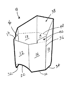
[0006] FIG. 1 is a perspective view of an example food holder in an opened,
vertical
position.
[0007] FIG. 2 is a plan view of the food holder in FIG. 1 in a flattened
position.
[0008] FIG. 3 is a side view of the food holder in FIG. 1.
[0009] FIG. 4 is a front view of the food holder in FIG. 1.
[0010] FIG. 5 is an unfolded view of a blank of the food holder in FIG. 1
[0011] FIG. 6 illustrates an unfolded view of a blank for an alternative
embodiment
of the food holder.
- 3 -
Date Recue/Date Received 2020-05-29
Attorney Docket No. 21088-149241
DETAILED DESCRIPTION
[0012] Described herein is a food holder 10 for receiving and supporting a
substantially cylindrical food product in a vertical orientation. As will be
recognized,
certain food products including a filling rolled into an edible wrap such as a
flat bread
like pita, naan, or tortilla (examples of which would include a burrito or a
chicken
wrap) or plant-based product such as lettuce or seaweed (examples of which
would
include lettuce wraps or sushi rolls) are cylindrical in nature, although such
foods may
be lumpy or oval such that they are not perfectly cylindrical. Referring to
FIGS. 1-5,
food holder 10 includes a forward panel 12, a rear panel 14, two front-side
panels 16,
and two back-side panels 18. Other embodiments of the present disclosure may
include
a different number of panels including, but not limited to, five, seven,
eight, nine, and
ten.
[0013] The food holder 10 further includes a bottom member 20 pivotally
coupled
to a bottom edge 22 of the forward panel 12 and a bottom edge 24 of the rear
panel 14.
The bottom member 20 includes a foldline 26 that substantially bisects the
bottom
member 20 such that the bottom member has a first section 28 and a second
section 30
of approximately equal area. In some embodiments of the present disclosure,
the
bottom member 20 may have more than one foldline 26. The bottom member 20 acts
as
a tension bridge connector and increases the structural integrity of the food
holder 10.
[0014] In some forms of the present disclosure, the foldline 26 may divide
the
bottom member 20 into a first section 28 and second section 30 but not bisect
the bottom
member 20 resulting a first section 28 and a second section 30 that are not
substantially
equal in area. Arranging the folding 26 such that it does not bisect the
bottom
member20 may allow the food holder 10 to fold flat when not in use, e.g., to
accommodate differences in height between the bottom edge 22 and the bottom
edge
24. The foldline 26 shown in FIGS. 2 and 5 is substantially parallel to the
bottom edge 22
of the forward panel 12 and the bottom edge 24 of the rear panel 14 (i.e.,
parallel within
- 4 -
Date Recue/Date Received 2020-05-29
Attorney Docket No. 21088-149241
the accuracies afforded by the materials used to form the food holder 10 and
adequate
to allow the food holder 10 to fold flat when not in use).
[0015] When the distance between the forward panel 12 and the rear panel 14
is
reduced, for example when users squeeze those panels of the food holder using
their
hand, the bottom member 20 is configured to bend at the foldline 26 and
project
upwards into a space inside the food holder 10 between the forward panel 12,
the rear
panel 14, the two front-side panels 16 and the two back-side panels 18. When a
food
product is in the food holder 10, squeezing the food holder to reduce the
distance
between the forward panel 12 and the rear panel 14 causes the bottom member 20
to
project into the space and therefore tends to elevate the food product in a
direction
away from the bottom member 20 to allow a consumer to access a lower portion
of the
food product. In short, by squeezing the food holder 10, the consumer causes
the
bottom member 20 of the food holder 10 to elevate the food product, making it
possible
to eat portions of the food product even if the food product itself is shorter
than the two
front-side panels 16 or the two back-side panels 18 of the food holder 10. In
this way,
the food holder 10 is adaptable to improve a consumer's access to the bottom
portion of
the food product near the end of consumption, allowing the consumer to eat
portions of
the food product that are otherwise contained in the food holder 10.
[0016] The design of the bottom member 20 is advantageous over alternative
approaches. For example, one alternative would use a shutter-style bottom
having
separate flaps extending inward from the bottom edge of each panel, where the
flaps
interconnect to support the rolled food product. In this shutter-style design,
the rolled
food product may push the flaps outward causing them to open and may cause the
food product to spill out the bottom of the food holder. In addition, the
bottom surface
of a food holder with a shutter-style bottom tends not to be flat and
therefore may not
adequately hold the rolled food product in a vertical orientation when placed
on a flat
surface such as a tabletop. The shutter-style design lacks the ability to
adequately
elevate the food product near the end of consumption. In some instances, when
a
- 5 -
Date Recue/Date Received 2020-05-29
Attorney Docket No. 21088-149241
consumer attempts to elevate the rolled food product by pressing the shutter-
style flaps
into the interior of the food folder, the flaps move away from each other to
create an
opening in the bottom of the food holder. Such an opening may expose the
bottom of
the rolled food product and allow for leakage. Further, the cost of
manufacturing a
shutter-style design may be greater than the cost of manufacturing the
preferred, bridge
design.
[0017] As shown in FIGS. 1,3, and 4, the food holder 10 may be placed in an
opened, vertical position such that the forward panel 12 and rear panel 14 are
as far
apart as possible. In this opened, vertical orientation, a bottom edge 32 of
each of the
front-side panels 16 and a bottom edge 34 of each of the back-side panels 18
may
contact a surface and support the food holder 10. As illustrated, these bottom
edges 32,
34 are substantially perpendicular to a centerline of the food holder 10
extending
upward through the bottom member 20 into the space defined by the panels 12,
14, 16,
18 (i.e., perpendicular within the accuracies afforded by the materials used
to form the
food holder 10 and such that when it contains a food product the food holder
10 is
capable of resting on the bottom edges 32 and 34 without tipping over). When
the food
holder 10 is in the opened, vertical orientation, the bottom edges 32, 34 of
the front-side
panels 16 and back-side panels 18 extend lower than the bottom edge 22 of the
forward
panel 12 and the bottom edge 24 of the rear panel 14 so that bottom edges 32,
34 at least
partially contact the surface. The food holder 10, therefore, contacts the
surface at four
points, namely, the bottom edge 32 for each of two front-side panels 16 and
the bottom
edge 34 for each of the two back-side panels 18. These points of contact
create a plane
on which the food folder 10 rests, which results in increased stability when
the food
product is inserted. Such increased stability can assist in preventing
accidental tip-overs
to the food product. In some embodiments, substantially the entire lengths of
bottom
edges 32, 34 may contact a surface. In other embodiments, the bottom edges 32,
34 may
be curved, ridged, or scalloped such that the portions of the bottom edges 32,
34 that
contact a surface still form a plane on which the food holder 10 may rest.
- 6 -
Date Recue/Date Received 2020-05-29
Attorney Docket No. 21088-149241
[0018] In some embodiments, the bottom edge 22 of the forward panel 12 and
the
bottom edge 24 of the rear panel 14 are curved. As shown in FIG. 5, the bottom
edges 22
and 24 include a concave arcuate shape. The arcuate shape of the bottom edges
22 and
24 advantageously allows the bridge 20 to be pushed up through the vessel.
Although
the disclosed invention includes embodiments in which the bottom edges 22 and
24 of
may be substantially straight, that approach does not similarly encourage
upward
movement when the front panel 12 and rear panel 14 are squeezed together. In
aspects
of the present disclosure where the bottom edges 22 and 24 are curved, the
radius of the
curve is between 1 in. and 2in., and more preferably between about 1.25 in.
and about
1.75 in. In a preferred embodiment designed for a food product with a
circumference
between 7 and 10.5 inches, the radius of the curve is between about 1.3 in.
and about 1.6
in. The curved bottom edge 22 of the forward panel 12 and the curved bottom
edge 24
of the rear panel 14 are connected to the bottom member 20. By increasing the
curvature
of the bottom edge 22 and the bottom edge 24, the locking operation of the
bottom
member 20 is improved, which better supports a rolled food product when placed
in
the food holder.
[0019] In one embodiment of the present disclosure, the food holder 10 is
formed
from a single piece of paperboard. The paperboard should have a weight (as
measured
per 1000 sq. ft.) of at least 80 lbs. Preferred ranges include paperboard
weights between
about 90 lbs. and about 185 lbs., between about 100 lbs. and about 185 lbs.,
between
about 110 lbs. and 185 lbs., between about 120 lbs. and about 185 lbs. In an
embodiment
designed for a food product with a circumference between 7 and 10.5 in. and a
length of
less than 8 in., the preferred paperboard weight is between 130 lbs. and about
150 lbs.
The preferred range ensures the paperboard is heavy enough to support food
products
such as the burritos available in most chain restaurants, but thin enough such
that the
paperboard can be bent to form the food holder. In other embodiments, the food
holder
may encompass more than one piece of paperboard. In other embodiments of the
present disclosure, the food holder may be made from paper, synthetic paper,
- 7 -
Date Recue/Date Received 2020-05-29
Attorney Docket No. 21088-149241
cardboard, corrugated paper, aluminum, other types of metal, Styrofoam, other
types of
foam, polyethylene terephthalate, polypropylene, high-density polyethylene,
low-
density polyethylene, polycarbonate, other types of plastic or another
material provided
at a thickness that may fold but still retains sufficient rigidity to hold the
food product
in a vertical orientation. The thickness of the material required to support
the rolled
food product in the vertical orientation of the food holder will depend on the
type of
material. For example, a material with a greater tensile strength or stiffness
will require
less thickness than a material with lesser tensile strength or stiffness to
support a food
product of the same weight and dimensions.
[0020] Referring to FIG. 2, the bottom width of the forward panel 12 and a
bottom
width of the rear panel 14 each have a length L1 that is about 25% to about
75% a length
of the foldline L2. In the flattened position, the food holder 10 cannot stand
in a vertical
orientation without external support. In order to prepare the food holder 10
to receive a
substantially cylindrical food product from a flattened position, pressure is
applied to
two first vertical edges 36 which join each of the front-side panel 16 to the
back-side
panel 18. The applied pressure moves the forward panel 12 and the rear panel
14
further apart from each other while simultaneously drawing the front-side
panels 16
and the back-side panels 18 closer together, as well as causing the bottom
member
sections 28, 30 to move further apart. Additional upward pressure may be
applied to
the foldline 26 of the bottom member 20 such that the foldline 26 bends and
the bottom
member 20 projects into the space between the panels 12, 14, 16, 18. When this
projection occurs, the forward panel 12 and the rear panel 14 move closer
together
again. Once the bottom member 20 is projected into the space between the
panels 12, 14,
16, 18, pressure applied to the first vertical edges 36 prevents the bottom
member 20
from returning to the flattened position without additional, sufficient
downward force
to the bottom member. The flattened position of the food holder 10 in FIG. 2
facilitates
transportation and storage of the food holder before it is ready to use.
- 8 -
Date Recue/Date Received 2020-05-29
Attorney Docket No. 21088-149241
[0021] As shown in FIGS. 1-5, the front-side panels 16 and the back-side
panels 18
have angled panel corners 52, which reduces interference between the front-
side panels
16 and the forward panel 12, as well as between the back-side panels 18 and
the rear
panel 14, when the food holder 10 transitions from a flattened position to an
opened,
vertical position. FIG. 6 illustrates an alternative embodiment in which the
angled
corner 52 is formed by stamping a different angle between the outside edges
628 and
630 of the bottom member 20 and the angled corner 52. The embodiment
illustrated in
FIG. 6 provides greater clearance between the bottom member and the edges of
the
front-side panels 16 and back-side panels 18. The angled indent between the
outside
edges 628 and 630 and the angled corner 52 also improves manufacturability, by
allowing the food holder to be stamped using a single die-cut.
[0022] In some forms of the present disclosure, the food holder 10 also
includes a
tear-away portion 38. This tear-away portion 38 may partially surround the
substantially cylindrical food product when the food product is inserted into
to the
space defined by the panels 12, 14, 16, 18. In other embodiments, the tear-
away portion
may completely surround the sides of the food product but remain open at the
top to
allow a consumer to access that top portion. Some embodiments include means to
help
control propagation of tearing after initiation, such as perforations or other
areas of
weakness. In some embodiments, the tear-away portion 38 is defined by a line
of
perforations 40. As shown in FIG. 3, the line of perforations 40 may be
substantially
parallel to the bottom edges 32 of the two front-side panels 16 and the bottom
edges 34
two back-side panels 18. In other forms, the line of perforations 40 may not
be
substantially parallel to the bottom edges 32 of the two front-side panels 16
and to the
bottom edges 34 of the two back-side panels 18. For example, the tear-away
portion
may be configured in a spiral pattern to reveal one side of the food product
while still
surrounding another side of the food product. Some embodiments of the food
holder
include more than one tear-away potion. A consumer may remove the tear-away
portions from the rest of the food holder in stages (one at a time) as the
food product is
- 9 -
Date Recue/Date Received 2020-05-29
Attorney Docket No. 21088-149241
consumed or may choose to remove more than one tear-away portion at the same
time
to reveal a greater portion of the food product.
[0023] In some forms, the food holder 10 includes a tear-away portion 38
that is
coupled to three, four, five, six, seven, or eight panels; half the panels;
less than half the
panels; or greater than half the panels. In one embodiment, the tear-away
portion has a
substantially uniform height. In other embodiments, the height of the tear-
away portion
varies from one panel to another. This configuration is beneficial because it
supports the
cylindrical food product in the horizontal orientation (i.e., taller panels of
the tear-away
portion lie underneath the food product) but allow access for a consumer to
consume
the cylindrical food product.
[0024] Preferably, as seen in FIGS. 1-5, the height of the tear-away
portion 38
tapers from one panel to the next and does not traverse the entire width of a
front-side
panels 16. As shown, the tear-way portion 38 of the food holder 10 includes at
least one
tab 42 to facilitate the removal of the tear-away portion 38. The tab 42 forms
a small
strip of material with enough area such that a consumer can securely grasp the
tab 42 to
initiate the tear to remove the tear-away portion 38. In one form, the tab 42
has rounded
corners instead of the straight edges shown. In some examples the food holder
10
includes an attachment means such as perforations for securing the tabs 42 to
the
corresponding one of the two front-side panels 16. In some embodiments, the
tab may
not be connected to the panel underneath the tab but only to the tear-away
portion
directly adjacent to the tab. In some embodiments, notches or edge cuts are
provided as
a means to facilitate tear initiation. In embodiments where a tab or the like
is used, the
tab may be of the same material as the rest of the food holder or of a
different material.
[0025] In some embodiments, the tear-away portion includes a plurality of
securing
tabs extending from different positions at the top of the tear-away portion 38
toward
the centerline of the food holder, such that each of the plurality of securing
tabs assists
in stabilizing the food product within the food holder. In some forms, the
plurality of
securing tabs is equal to the number of panels. In other forms, the plurality
of securing
- 10 -
Date Recue/Date Received 2020-05-29
Attorney Docket No. 21088-149241
tabs is less than the number of panels. In yet other forms, the plurality of
securing tabs
is greater than the number of panels. In some embodiments which do not include
a tear-
away portion 38, the securing tabs may extend directly from the panels.
[0026] Referring to FIG. 3, a height Hi of the tear-away portion 38 joined
to the rear
panel 14 is at least 40% of a height H2 of the rear panel 14. In other
embodiments, the
total height of the tear-away portion(s) may be at least 10%, at least 20%, at
least 30%, at
least 50%, at least 60%, at least 70%, at least 80%, or at least 90% of the
height of the rear
panel. The specific ratio between Hi and H2 will depend on the length of the
food
product, which is preferably not be more than double the combined Hi and H2
height. If
the food is substantially more than double the combined Hi and H2 height, the
food
product tends to slump or fall over when placed in a vertical orientation
because the
weight of the food product needs to be distributed and supported by the food
holder.
The combined heights Hi and H2 will preferably be above the median height of
the food
product. The preferred embodiment illustrated in FIG. 3 is designed based on
food
products with lengths less than 8 in. In some forms of the present disclosure,
the
forward panel 12 may have a height H3 smaller than the combined height of the
height
Hi and H2. In other embodiments, the height H3 may be equal to the combined
height of
Hi and H2. Preferably, as shown in FIG. 3, the height H3 of the forward panel
12 is
substantially similar to that of the height H2 of the rear panel 14 to
facilitate eating the
food product when the tear-away portion 38 is removed. In other aspects, the
height H3
of the forward panel 12 is less than the height H2 of the rear panel 14.
[0027] As illustrated in FIGS. 4 and 5, the food holder 10 may be an
irregular shape
such that a bottom width Li of the forward panel 12 is less than a bottom
width L3 of the
two front-side panels 16 and the two back-side panels 18. In such an
embodiment, the
two front-side panels 16 and the two back-side panels 18 may be configured to
contact
the food product when the food product is placed in the space defined by
panels 12, 14,
16, 18. By increasing the width L3 of the front-side panels 16 and 18 relative
to the width
Li of the forward panel 12 and rear panel 14, the food holder better serves to
lock the
- 11 -
Date Recue/Date Received 2020-05-29
Attorney Docket No. 21088-149241
bottom member 20 in place upon expanding the food holder to receive a
cylindrical
food product.
[0028] As shown in FIG. 5, the food holder 10 may have a tapered shape
where an
angle e of between about 90 and about 95 degrees is formed between the bottom
edges
32 of the front-side panels 16 and a respective first vertical edge 44 and
second vertical
edge 46 of the forward panel 12. The tapered shape may include an angle Q of
between
about 90 and about 95 degrees formed between the bottom edges 34 of the back-
side
panels 18 and a respective first vertical edge 48 and second vertical edge 50
of the rear
panel 14. In some embodiments, the tapered shape includes an angle p of
between
about 90 and about 95 degrees formed between the bottom edges 32 of the front-
side
panels 16 and the respective vertical edges 36 joining the front-side panels
16 to the two
back-side panels 18.
[0029] The tapered, irregular shape of the food holder helps to provide
rigidity to
the food holder when a product resides in the space between the panels such
that the
food holder tends to remain in the vertical orientation and that the bottom
member
supports the food product within the space between the panels. Specifically,
the taper of
the food holder provides increased structural integrity when the food product
inserted
into the food holder. The weight of the food product provides increased inward
pressure on the panels and prevents the bottom member being pushed back
outside the
space between the panels. Further, by selecting lengths for the forward panel
and the
rear panel relative to the lengths of the front-side and back-side panels, the
front-side
panels and the back-side panels substantially contact and support the food
product. In
embodiments with sufficient taper to help support the food product, securing
tabs may
not be necessary to stabilize the food product within the food holder.
Removing the
securing tabs is an advantage of the tapered shape, because the securing tabs
may cause
resistance against the rolled food product when the food product is elevated
out of the
food holder by the bottom member.
- 12 -
Date Recue/Date Received 2020-05-29
Attorney Docket No. 21088-149241
[0030] The food holder may have varying sizes to conform to varying sizes
of
cylindrical food products, for example, a smaller burrito to be consumed by a
child and
a regular burrito to be consumed by an adult. When in an opened, vertical
position, the
height of rear panel 14 of the food holder 10 combined with any tear-away
portions 38
above the rear panel, as a percentage of the length of the rolled food
product, may be
between about 30% and about 100%, between about 35% and about 100%, between
about 40% and about 100%, between about 45% and about 100%, between about 50%
and about 100%, between about 55% and about 100%, between about 60% and about
100%, between about 65% and about 100%, between about 70% and about 100%,
between about 75% and about 100%, between about 50% and about 75%, between
about
50% and about 70%, between about 50% and about 65%, between about 50% and
about
60% or, preferably, about 65% to about 70% the length of the rolled food
product. As
noted above, if the food is substantially more than double the combined Hi and
H2
height shown in FIG. 3, the food product tends to slump or fall over when
placed in a
vertical orientation. Such a proportionality allows a consumer access to the
rolled food
product while still providing adequate support to keep the food product in a
vertical
position.
[0031] When in a flattened position, the food holder 10 may have a total
width L4 of
between about 3 in. and 6 in., between about 3.5 in. and about 5.5 in.,
between about 4
in. and about 5.5 in., between about 4.5 in. and about 5.5 in., and preferably
between
about 4.8 in. and about 5.3 in. In some embodiments, the length L2 of the
foldline 26, as a
percentage of the total width L4 of the food holder 10, may be between about
55% to
about 65% or about 60%, which may assist in increasing the structural
integrity of the
food holder 10.
[0032] FIG. 6 illustrates an alternative embodiment of the invention, which
shares
many features with the embodiment illustrated in FIGS. 1-5. Reference numerals
shared
between FIG. 6 and FIGS. 1-5 correspond to features discussed above. FIG. 6
illustrates
an angle 01 between outside edges 628 of the bottom member 20 and the tapered
- 13 -
Date Recue/Date Received 2020-05-29
Attorney Docket No. 21088-149241
portion 632 of the bottom edge 32 of front-side panels 16. Similarly, an angle
02 exists
between outside edges 630 of the bottom member 20 and the tapered portion 634
of the
bottom edge 34 of front-side panels 18. The angles 01 and 02 make it easier to
open the
food holder with one hand. Without the angled relief, the edges 628 and 632
and the
edges 630 and 634 tend to stick together, which generally prevents the food
holder from
expanding from a collapsed position (as shown in FIG. 2) to an open position
(as shown
in FIG. 1). The angles 01 and 02 may be substantially identical, or they may
differ to
accommodate asymmetry in the bottom member 20. As shown in FIG. 6, angles 01
and
02 may be between about 15 and about 30 degrees and preferably will be between
20
and 25 degrees. Smaller angles for 01 and (1)2 may make tooling more
complicated and
may reduce the effectiveness of including the angled relief. Larger angles for
01 and 02
may make the food holder less stable by reducing the footprint formed by the
edges 32
and 34.
[0033] Each of the various features described above may be used in
combination
with any other compatible features described above. Various aspects of the
article
described herein are further described in the following claims.
- 14 -
Date Recue/Date Received 2020-05-29