Sélection de la langue

Search

Sommaire du brevet 3087054 

Énoncé de désistement de responsabilité concernant l'information provenant de tiers

Une partie des informations de ce site Web a été fournie par des sources externes. Le gouvernement du Canada n'assume aucune responsabilité concernant la précision, l'actualité ou la fiabilité des informations fournies par les sources externes. Les utilisateurs qui désirent employer cette information devraient consulter directement la source des informations. Le contenu fourni par les sources externes n'est pas assujetti aux exigences sur les langues officielles, la protection des renseignements personnels et l'accessibilité.

Disponibilité de l'Abrégé et des Revendications

L'apparition de différences dans le texte et l'image des Revendications et de l'Abrégé dépend du moment auquel le document est publié. Les textes des Revendications et de l'Abrégé sont affichés :

  • lorsque la demande peut être examinée par le public;
  • lorsque le brevet est émis (délivrance).
(12) Brevet: (11) CA 3087054
(54) Titre français: PIEGE A RONGEURS ELECTRONIQUE AVEC CIRCUIT SURVOLTEUR POUR DES PERFORMANCES DE PIEGE AMELIOREES PENDANT LA DUREE DE VIE DE LA BATTERIE
(54) Titre anglais: ELECTRONIC RODENT TRAP WITH VOLTAGE BOOSTER CIRCUIT FOR IMPROVED TRAP PERFORMANCE OVER THE LIFE OF THE BATTERY
Statut: Octroyé
Données bibliographiques
(51) Classification internationale des brevets (CIB):
  • A01M 23/38 (2006.01)
  • A01M 19/00 (2006.01)
  • A01M 23/12 (2006.01)
  • A01M 31/00 (2006.01)
  • G11C 5/14 (2006.01)
(72) Inventeurs :
  • WANNINGER, DANIEL (Etats-Unis d'Amérique)
  • MURPHY, KEVIN (Etats-Unis d'Amérique)
(73) Titulaires :
  • WOODSTREAM CORPORATION (Etats-Unis d'Amérique)
(71) Demandeurs :
  • WOODSTREAM CORPORATION (Etats-Unis d'Amérique)
(74) Agent: PIASETZKI NENNIGER KVAS LLP
(74) Co-agent:
(45) Délivré: 2024-03-19
(86) Date de dépôt PCT: 2018-12-18
(87) Mise à la disponibilité du public: 2019-07-04
Requête d'examen: 2021-10-28
Licence disponible: S.O.
(25) Langue des documents déposés: Anglais

Traité de coopération en matière de brevets (PCT): Oui
(86) Numéro de la demande PCT: PCT/US2018/066261
(87) Numéro de publication internationale PCT: WO2019/133340
(85) Entrée nationale: 2020-06-25

(30) Données de priorité de la demande:
Numéro de la demande Pays / territoire Date
62/610,374 Etats-Unis d'Amérique 2017-12-26

Abrégés

Abrégé français

L'invention concerne un circuit et un procédé pour amplifier l'entrée de tension à la grille d'un commutateur MOSFET utilisé dans un piège à rongeur électronique. En amplifiant la tension à la grille, le MOSFET peut être complètement mis en marche pour activer un cycle de mise à mort efficace dans le piège à rongeur électronique même lorsque la tension de la batterie du piège a chuté à un niveau qui serait sinon insuffisant pour activer complètement le MOSFET.


Abrégé anglais

A circuit and method for boosting the voltage input to the gate of a MOSFET switch used in an electronic rodent trap is provided. By boosting the voltage to the gate, the MOSFET can be fully turned on to activate an effective killing cycle in the electronic rodent trap even when the trap's battery voltage has dropped to a level that would otherwise be insufficient to fully activate the MOSFET.

Revendications

Note : Les revendications sont présentées dans la langue officielle dans laquelle elles ont été soumises.


9
THE EMBODIMENTS OF THE INVENTION IN WHICH AN EXCLUSIVE
PROPERTY OR PRIVILEGE IS CLAIMED ARE DEFINED AS FOLLOWS:
1. An electronic rodent trap for electrocuting rodents comprising:
at least one battery having an output voltage adequate to operate the trap and
kill a
rodent when said at least one battery is fully charged, said output voltage
declining over a
life of said at least one battery;
a micro-controller powered by said at least one battery;
a circuit for boosting the output voltage of said at least one battery, said
circuit
including a multi-stage charge pump driven by a pulse train from said micro-
controller and
having outputs of each stage connected in series for generating an output
having a voltage
higher than said battery output voltage;
killing plates coupled to a transformer for electrocuting a rodent when
activated;
and
a drive circuit connected to the output of said circuit for boosting an output
voltage
of said at least one battery including said charge pump and to a high-voltage
MOSFET
coupled to the transformer, the MOSFET when turned on generating a high
voltage by
rapidly switching a ground return path of the transfoimer to create a flyback
voltage that
activates the killing plates, the higher voltage output of the charge pump
fully activating
the MOSFET even when the output voltage of the at least one battery has
dropped to a
level insufficient to fully turn on the MOSFET, thereby extending the life of
the at least
one battery.
2. The electronic rodent trap as set forth in claim 1, wherein the charge
pump includes
a plurality of diodes and a plurality of capacitors configured in a plurality
of stages, each
stage being driven in turn to add a voltage supplied to the micro-controller
to the battery
output voltage.
3. The electronic rodent trap as set forth in claim 1, wherein high-voltage
MOSFET
requires a gate voltage of approximately 5 volts to partially activate and 10
volts to fully
activate.
Date recue/Date received 2023-05-04

10
4. The electronic rodent trap as set forth in claim 1, further comprising a
voltage
regulator arranged between the at least one battery and an input of the micro-
controller for
regulating a power supply voltage provided to the micro-controller.
5. The electronic rodent trap as set forth in claim 4, wherein the power
supply voltage
is different than the battery voltage.
6. The electronic rodent trap as set forth in claim 2, wherein the
plurality of diodes are
arranged in series.
7. The electronic rodent trap of claim 6, wherein the plurality of
capacitors are
arranged in parallel, each capacitor connected on a first end to a respective
input/output pin
of the micro-controller and connected on a second end between an output of one
of the
plurality of diodes and an input of another one of the plurality of diodes.
8. The electronic rodent trap of claim 7, wherein the first end of each of
the plurality
of capacitors is directly connected to a respective input/output pin of the
micro-controller
and the second end of each of the plurality of capacitors is directly
connected between an
output of one of the plurality of diodes and an input of another one of the
plurality of
diodes.
9. A battery-operated electronic rodent trap having a transformer coupled
to killing
plates, the trap comprising a MOSFET switch coupled to the transformer and a
multi-stage
charge pump driven by a pulse train that is generated by a micro-controller,
the multi-stage
charge pump boosting a voltage input to a gate of the MOSFET so that the
MOSFET is
fully turned on and a flyback voltage from the transfoliner, used to activate
the killing
plates to electrocute a rodent, is maintained even when the battery voltage
has dropped to a
level insufficient to fully activate the MOSFET.
10. The battery-operated electronic rodent trap as set forth in claim 9,
wherein outputs
of each of a plurality of stages of the multi-state charge pump are connected
in series to an
input of a drive circuit for generating the voltage input to the gate of the
MOSFET.
Date recue/Date received 2023-05-04

11
11. An electronic rodent trap, comprising:
a battery;
a micro-controller powered by the battery;
a voltage regulator arranged between the battery and the micro-controller;
a multi-stage charge pump having an input connected to the battery, including:
a plurality of diodes arranged in series, a first diode of the plurality of
diodes having an input connected to the battery; and
a plurality of capacitors arranged in parallel, each capacitor of the
plurality
of capacitors being connected on a first end to a respective input/output
terminal of
the microcontroller and connected on a second end between an output of one of
the
plurality of diodes and an input of another one of the plurality of diodes,
the charge
pump driven by a pulse train from the micro-controller for generating an
output
having a voltage higher than the battery output voltage;
a drive circuit having an input connected to an output of a last one of the
plurality
of diodes of the charge pump;
a high voltage field-effect transistor connected between an output of the
drive
circuit and a transformer; and
killing plates coupled to the transformer for electrocuting a rodent when
activated,
the transistor rapidly switching a ground return path of the transformer to
create a flyback
voltage for activating the killing plates.
12. The electronic rodent trap of claim 11, wherein an output voltage of
the multi-stage
charge pump is approximately equal to:
(battery voltage) + (n*micro-controller voltage)
wherein n is the number of stages of the multi-stage charge pump, and the
micro-controller
voltage is the voltage supplied to the micro-controller by the voltage
regulator.
Date recue/Date received 2023-05-04

Description

Note : Les descriptions sont présentées dans la langue officielle dans laquelle elles ont été soumises.

CA 03087054 2020-06-25
WO 2019/133340
PCT/US2018/066261
- 1 -
ELECTRONIC RODENT TRAP WITH VOLTAGE BOOSTER
CIRCUIT FOR IMPROVED TRAP PERFORMANCE
OVER THE LIFE OF THE BATTERY
This application claims the priority of U.S.
provisional application Serial No. 62/610,374 filed December 26,
2017.
BACKGROUND OF THE INVENTION
Field of the Invention
The present invention is related to the field of pest
control and, more particularly, to a device and method for
increasing the effective life span of batteries used in
conjunction with electronic rodent traps.
Description of the Related Art
One defining characteristic of any battery powered
device is the life of the battery. In connection with pest
control, many electronic rodent traps rely on battery power to

CA 03087054 2020-06-25
WO 2019/133340
PCT/US2018/066261
- 2 -
dispatch rodents and, to an increasing extent, to enable the
trap for wireless communication. Both of these activities can
be taxing on the battery, requiring the consumer to replace the
batteries often.
With respect to the rodent dispatch function of an
electronic rodent trap, many existing electronic rodent trap
designs use a power N-channel metal-oxide-semiconductor field-
effect-transistor (MOSFET) as a switch. Power N-channel MOSFETs
are electronic devices typically possessing three pins including
a gate, drain, and source pin. When a voltage is applied to the
gate, current can then pass from the drain pin to the source
pin. The power N-channel MOSFET switch generates a high voltage
by rapidly switching the ground return path for a transformer
on and off. The switching action creates a flyback voltage from
the transformer on the order of thousands of volts, which is
capable of killing a rodent.
The voltage applied at the gate must be sufficiently
high to fully turn on the MOSFET. In existing electronic rodent
trap designs, the voltage applied to the gate is typically
provided by the battery, which is nominally 6V. For effective
function, a minimum output voltage is required across the plates
of an electronic trap to consistently shock both mice and rats.
With a small drop in battery voltage, however, the MOSFET no

CA 03087054 2020-06-25
WO 2019/133340
PCT/US2018/066261
- 3 -
longer fully turns on, and the flyback voltage from the
transformer is significantly reduced.
Hence, a common problem in existing traps on the
market is the inability to maintain this minimum voltage
consistently over the life of the batteries. As the battery
voltage drops, the efficacy of the trap will also drop. Therefore
a need exists for a way to maintain the output voltage at a
sufficiently high level to kill a rodent over a longer percentage
of the total life of the batteries to increase the cost
effectiveness of electronic rodent trap operation.
SUMMARY OF THE INVENTION
In view of the foregoing, the present invention is
directed to a circuit and method for boosting the voltage input
to the gate of a MOSFET switch used in a battery-powered
electronic rodent trap.
The circuit includes a multi-stage
charge pump driven by a pulse train that is generated by a micro-
controller. By boosting the voltage to the gate, the MOSFET can
be fully turned on to activate an effective killing cycle in the
electronic rodent trap even when the trap's battery voltage is
low.

CA 03087054 2020-06-25
WO 2019/133340
PCT/US2018/066261
- 4 -
The present invention is also directed to an
electronic rodent trap that includes a charge pump circuit to
provide a higher voltage to the drive circuit that is used to
generate the high voltage required for the trap to electrocute
the rodent.
Accordingly, it is an object of the present invention
to provide a voltage booster circuit for a battery-powered
electronic rodent trap that maintains the efficacy of trap
operation for the dispatching of rodents over a longer portion
of the life of the batteries.
Another object of the present invention is to provide
a battery-operated electronic rodent trap using a MOSFET switch
that includes a multi-stage charge pump driven by a pulse train
that is generated by a micro-controller, the multi-stage charge
pump serving to boost the voltage to the gate of the MOSFET so
that the MOSFET is fully turned on and the flyback voltage from
the transformer is maintained even when the battery voltage has
dropped.
A further object of the present invention is to
provide a battery-operated electronic rodent trap that is more
cost effective in operation, being configured to maintain the
output voltage of the trap's electronic killing circuit at a

CA 03087054 2020-06-25
WO 2019/133340
PCT/US2018/066261
- 5 -
suffici ent 1 y high level to kill a rodent over a longer percentage
of the total life of the batteries.
These together with other objects and advantages which
will become subsequently apparent reside in the details of
construction and operation as more fully hereinafter described
and claimed, reference being had to the accompanying drawings
forming a part hereof, wherein like numerals refer to like parts
throughout.
BRIEF DESCRIPTION OF THE DRAWINGS
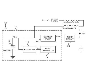
Figure 1 is a block diagram of a circuit having a
micro-controller-driven multi-stage charge pump for use with a
battery-powered electronic rodent trap in accordance with the
present invention.
Figure 2 is a block diagram of the components of a
battery-powered electronic rodent trap that includes the circuit
shown in Figure 1.
DETAILED DESCRIPTION OF THE PREFERRED EMBODIMENTS
It is to be understood that the embodiments described
herein are disclosed by way of illustration only. It
is not

CA 03087054 2020-06-25
WO 2019/133340
PCT/US2018/066261
- 6 -
intended that the invention be limited in its scope to the
details of construction and arrangement of components set forth
in the following description or illustrated in the drawings.
Also, in describing the preferred embodiments, specific
terminology will be resorted to for the sake of clarity. It is
to be understood that each specific term includes all technical
equivalents which operate in a similar manner to accomplish a
similar purpose.
As shown in Figure 1, the present invention includes
a circuit generally designated by reference numeral 10 for
boosting the output voltage of a battery or batteries 12 within
the circuit. The circuit 10 includes a multi-stage charge pump
14 that includes diodes D1, D2, Dn and capacitors Cl, C2, Cn to
generate an output voltage, Vchg, that is higher than the input
voltage, Vbat, in a manner known in the art for charge pump
circuits.
The charge pump 14 is driven by a pulse train that is
generated by the input/output (I/O) pins of a micro-controller
16.
The micro-controller 16 is, in turn, powered by a power
supply, Vcc, which is derived from the battery or batteries 12
as regulated by regulator 18. The power supply, Vcc, to the
micro-controller 16, may be identical to, or different from, the
battery voltage, Vbat.

CA 03087054 2020-06-25
WO 2019/133340
PCT/US2018/066261
- 7 -
Each stage in the charge pump 14 is driven in turn to
add the voltage supplied to the micro-controller 16 to the
battery voltage so that, for n stages, the output of the charge
pump, Vchg, is approximately equal to:
(battery voltage) + (n * micro-controller voltage)
as shown in Figure 1.
As shown by the electronic rodent trap generally
designated by reference numeral 100 in Figure 2, the output of
the multi-stage charge pump 14, Vchg, is connected to a drive
circuit 20 and MOSFET Q1 used to generate the high voltage
required to activate killing plates 22 used to electrocute the
rodent.
According to one embodiment, the high-voltage MOSFET
Q1 requires a gate voltage of approximately 5 volts to partially
activate, and 10 volts to fully activate. Typical battery
voltages used in electronic rodent traps like trap 100 are on
the order of 6 volts with fresh batteries, with the voltage
level decreasing as the batteries discharge. The charge pump
circuit 14 as incorporated within the trap 100 according to the
present invention allows the trap to generate a greater output
voltage by more fully activating the power MOSFET Q1 when it has
fresh batteries and to continue to activate the high-voltage

CA 03087054 2020-06-25
WO 2019/133340
PCT/US2018/066261
- 8 -
MOSFET Ql, by boosting voltage to the gate thereof, even when
the battery voltage as dropped to a level that would in itself
be insufficient for trap activation and rodent dispatch. As a
result, the flyback voltage from the transformer can be
sustained even when the battery voltage itself is too low to
fully switch on the MOSFET.
The foregoing descriptions and drawings should be
considered as illustrative only of the principles of the
invention.
The invention may be configured in a variety of
shapes and sizes and is not limited by the dimensions of the
preferred embodiment.
Numerous applications of the present
invention will readily occur to those skilled in the art.
Therefore, it is not desired to limit the invention to the
specific examples disclosed or the exact construction and
operation shown and described.
Rather, all suitable
modifications and equivalents may be resorted to, falling within
the scope of the invention.

Dessin représentatif
Une figure unique qui représente un dessin illustrant l'invention.
États administratifs

Pour une meilleure compréhension de l'état de la demande ou brevet qui figure sur cette page, la rubrique Mise en garde , et les descriptions de Brevet , États administratifs , Taxes périodiques et Historique des paiements devraient être consultées.

États administratifs

Titre Date
Date de délivrance prévu 2024-03-19
(86) Date de dépôt PCT 2018-12-18
(87) Date de publication PCT 2019-07-04
(85) Entrée nationale 2020-06-25
Requête d'examen 2021-10-28
(45) Délivré 2024-03-19

Historique d'abandonnement

Il n'y a pas d'historique d'abandonnement

Taxes périodiques

Dernier paiement au montant de 210,51 $ a été reçu le 2023-11-22


 Montants des taxes pour le maintien en état à venir

Description Date Montant
Prochain paiement si taxe applicable aux petites entités 2024-12-18 100,00 $
Prochain paiement si taxe générale 2024-12-18 277,00 $

Avis : Si le paiement en totalité n'a pas été reçu au plus tard à la date indiquée, une taxe supplémentaire peut être imposée, soit une des taxes suivantes :

  • taxe de rétablissement ;
  • taxe pour paiement en souffrance ; ou
  • taxe additionnelle pour le renversement d'une péremption réputée.

Les taxes sur les brevets sont ajustées au 1er janvier de chaque année. Les montants ci-dessus sont les montants actuels s'ils sont reçus au plus tard le 31 décembre de l'année en cours.
Veuillez vous référer à la page web des taxes sur les brevets de l'OPIC pour voir tous les montants actuels des taxes.

Historique des paiements

Type de taxes Anniversaire Échéance Montant payé Date payée
Enregistrement de documents 2020-06-25 100,00 $ 2020-06-25
Le dépôt d'une demande de brevet 2020-06-25 400,00 $ 2020-06-25
Taxe de maintien en état - Demande - nouvelle loi 2 2020-12-18 100,00 $ 2020-12-02
Taxe de maintien en état - Demande - nouvelle loi 3 2021-12-20 100,00 $ 2021-10-28
Requête d'examen 2023-12-18 816,00 $ 2021-10-28
Taxe de maintien en état - Demande - nouvelle loi 4 2022-12-19 100,00 $ 2022-11-22
Taxe de maintien en état - Demande - nouvelle loi 5 2023-12-18 210,51 $ 2023-11-22
Taxe finale 416,00 $ 2024-02-06
Titulaires au dossier

Les titulaires actuels et antérieures au dossier sont affichés en ordre alphabétique.

Titulaires actuels au dossier
WOODSTREAM CORPORATION
Titulaires antérieures au dossier
S.O.
Les propriétaires antérieurs qui ne figurent pas dans la liste des « Propriétaires au dossier » apparaîtront dans d'autres documents au dossier.
Documents

Pour visionner les fichiers sélectionnés, entrer le code reCAPTCHA :


Pour visualiser une image, cliquer sur un lien dans la colonne description du document. Pour télécharger l'image (les images), cliquer l'une ou plusieurs cases à cocher dans la première colonne et ensuite cliquer sur le bouton "Télécharger sélection en format PDF (archive Zip)" ou le bouton "Télécharger sélection (en un fichier PDF fusionné)".

Liste des documents de brevet publiés et non publiés sur la BDBC .

Si vous avez des difficultés à accéder au contenu, veuillez communiquer avec le Centre de services à la clientèle au 1-866-997-1936, ou envoyer un courriel au Centre de service à la clientèle de l'OPIC.


Description du
Document 
Date
(yyyy-mm-dd) 
Nombre de pages   Taille de l'image (Ko) 
Abrégé 2020-06-25 2 61
Revendications 2020-06-25 2 64
Dessins 2020-06-25 1 13
Description 2020-06-25 8 196
Dessins représentatifs 2020-06-25 1 7
Rapport prélim. intl. sur la brevetabilité reçu 2020-06-25 12 807
Rapport prélim. intl. sur la brevetabilité reçu 2020-06-25 10 493
Rapport de recherche internationale 2020-06-25 1 54
Demande d'entrée en phase nationale 2020-06-25 12 532
Page couverture 2020-09-01 1 36
Paiement de taxe périodique 2020-12-02 1 33
Paiement de taxe périodique 2021-10-28 1 33
Requête d'examen 2021-10-28 3 103
Demande d'examen 2023-01-11 3 156
Modification 2023-05-04 15 595
Revendications 2023-05-04 3 186
Taxe finale 2024-02-06 4 115
Dessins représentatifs 2024-02-20 1 7
Page couverture 2024-02-20 1 41
Certificat électronique d'octroi 2024-03-19 1 2 527