Sélection de la langue

Search

Sommaire du brevet 3091347 

Énoncé de désistement de responsabilité concernant l'information provenant de tiers

Une partie des informations de ce site Web a été fournie par des sources externes. Le gouvernement du Canada n'assume aucune responsabilité concernant la précision, l'actualité ou la fiabilité des informations fournies par les sources externes. Les utilisateurs qui désirent employer cette information devraient consulter directement la source des informations. Le contenu fourni par les sources externes n'est pas assujetti aux exigences sur les langues officielles, la protection des renseignements personnels et l'accessibilité.

Disponibilité de l'Abrégé et des Revendications

L'apparition de différences dans le texte et l'image des Revendications et de l'Abrégé dépend du moment auquel le document est publié. Les textes des Revendications et de l'Abrégé sont affichés :

  • lorsque la demande peut être examinée par le public;
  • lorsque le brevet est émis (délivrance).
(12) Brevet: (11) CA 3091347
(54) Titre français: ASSEMBLAGE DE SUPPORT DE FIXATION RAPIDE
(54) Titre anglais: FAST FIT BRACKET ASSEMBLY
Statut: Octroyé
Données bibliographiques
(51) Classification internationale des brevets (CIB):
  • F16B 1/00 (2006.01)
  • A47G 1/20 (2006.01)
  • A47G 29/00 (2006.01)
  • A47K 10/12 (2006.01)
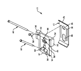
(72) Inventeurs :
  • ELLIOTT, TIMOTHY (Etats-Unis d'Amérique)
(73) Titulaires :
  • KENNEY MANUFACTURING COMPANY (Etats-Unis d'Amérique)
(71) Demandeurs :
  • KENNEY MANUFACTURING COMPANY (Etats-Unis d'Amérique)
(74) Agent: PARLEE MCLAWS LLP
(74) Co-agent:
(45) Délivré: 2021-06-22
(22) Date de dépôt: 2020-08-27
(41) Mise à la disponibilité du public: 2021-02-28
Requête d'examen: 2020-08-27
Licence disponible: S.O.
(25) Langue des documents déposés: Anglais

Traité de coopération en matière de brevets (PCT): Non

(30) Données de priorité de la demande:
Numéro de la demande Pays / territoire Date
16/556,968 Etats-Unis d'Amérique 2019-08-30

Abrégés

Abrégé français

ABRÉGÉ DE LINVENTION [0033] Un assemblage de support comprend une plaque métallique frappée par une matrice, un ensemble guide/clou en plastique moulé configuré pour sajuster sur la plaque métallique frappée par une matrice, lensemble guide/clou en plastique moulé comprenant trois ouvertures espacées, chacune des ouvertures étant configurée selon un angle par rapport à une surface centrale de lensemble guide/clou, la surface centrale comprenant deux ailes opposées supérieures et une aile centrale inférieure configurée pour recevoir et fixer un accessoire, et des clous de finition communs, les clous de finition communs utilisés pour fixer la plaque métallique frappée par la matrice et lensemble guide/clou en plastique moulé, lorsquils sont joints ensemble, à une surface verticale. 9 Date reçue/Date Received 2020-08-27


Abrégé anglais


ABSTRACT OF THE INVENTION
[0033] A bracket assembly includes a die struck metal plate, a
molded plastic guide/nail set configured to fit over the die
struck metal plate, the molded plastic guide/nail set
including three spaced apart apertures, each of the apertures
configured at an angle with respect to a central surface of
the guide/nail set, the central surface comprising two upper
opposing wings and a lower central wing configured to receive
and secure an accessory, and common finish nails, the common
finish nails used to secure the die struck metal plate and the
molded plastic guide/nail set, when joined together, to a
vertical surface.
9
Date Recue/Date Received 2020-08-27

Revendications

Note : Les revendications sont présentées dans la langue officielle dans laquelle elles ont été soumises.


WHAT IS CLAIMED IS:
1. A bracket assembly comprises:
a die struck metal plate;
a molded plastic guide set configured to fit over
the die struck metal plate, the molded plastic guide set
including three spaced apart apertures, each of the apertures
configured at an obtuse angle with respect to a central
surface of the guide, the central surface comprising two upper
opposing wings and a lower central wing configured to receive
and secure an accessory; and
common nails, the common nails used to secure the
die struck metal plate and the molded plastic guide set, when
joined together, to a vertical surface.
2. The bracket assembly of claim 1 wherein the obtuse
angle enables the common nails to be driven through the die
struck metal plate and vertical surface at an outwardly and at
a downward angle, providing a solid anchoring to the vertical
surface.
3. The bracket assembly of claim 1 wherein the accessory
is selected from the group consisting of hooks, towel bars,
towel rings, and toilet paper rings.
4. The bracket assembly of claim 1 wherein the vertical
surface is a drywall surface.
5. The bracket assembly of claim 1 wherein the vertical
surface is a wood surface.
7
Date Recue/Date Received 2020-08-27

6. The bracket assembly of claim 1 wherein a height of
the die struck metal plate is 1.76 inches.
7. The bracket assembly of claim 1 wherein a width of a
widest section of the molded plastic guide is 1.40 inches.
8. The bracket assembly of claim 1 wherein the accessory
is secured to the molded plastic guide with a set screw.
9. A bracket assembly comprises:
a die struck metal plate;
a molded plastic guide set configured to fit over
the die struck metal plate, the molded plastic guide set
including three spaced apart apertures, each of the apertures
configured at an obtuse angle with respect to a central
surface of the molded plastic guide set, the central surface
comprising two upper opposing wings and a lower central wing
configured to receive and secure an accessory; and
common nails, the common nails used to secure the
die struck metal plate and the molded plastic guide set when
joined together, to a vertical surface,
the die struck metal plate including three apertures
that are configured to align with the three apertures of the
molded plastic guide set.
8
Date Recue/Date Received 2020-08-27

Description

Note : Les descriptions sont présentées dans la langue officielle dans laquelle elles ont été soumises.

FAST FIT BRACKET ASSEMBLY
FIELD OF THE INVENTION
[001] The present invention relates generally to brackets,
and more particularly to a fast fit bracket assembly.
BACKGROUND OF THE INVENTION
[002] In general, a bracket is an overhanging member that
projects from a structure (such as a wall) and is usually
designed to support a vertical load or to strengthen an angle.
There are a variety of brackets that are available on the
market but none provide a fast and easy procedure for mounting
hardware.
SUMMARY OF THE INVENTION
[003] The following presents a simplified summary of the
innovation in order to provide a basic understanding of some
aspects of the invention. This summary is not an extensive
overview of the invention. It is intended to neither identify
key or critical elements of the invention nor delineate the
scope of the invention. Its sole purpose is to present some
concepts of the invention in a simplified form as a prelude to
the more detailed description that is presented later.
[004] In an aspect, the invention features a bracket assembly
including a die struck metal plate, a molded plastic
guide/nail set configured to fit over the die struck metal
plate, the molded plastic guide/nail set including three
spaced apart apertures, each of the apertures configured at an
angle with respect to a central surface of the guide/nail set,
the central surface comprising two upper opposing wings and a
lower central wing configured to receive and secure an
accessory, and common finish nails, the common finish nails
used to secure the die struck metal plate and the molded
plastic guide/nail set, when joined together, to a vertical
surface.
1
Date Recue/Date Received 2020-08-27

[005] In another aspect, the invention features a method
including providing a bracket assembly, the bracket assembly
including a die struck metal plate and a molded plastic
guide/nail set configured to fit over the die struck metal
plate, the molded plastic guide/nail set including three
spaced apart apertures, each of the apertures configured at an
angle with respect to a central surface of the guide/nail set,
the central surface comprising two upper opposing wings and a
lower central wing configured to receive and secure an
accessory, driving a first common finish nail into a lower
aperture on the bracket assembly to fix and position the
bracket assembly on a vertical surface, driving second and
third common finishing nails downwardly and outwardly into
spaced apart upper apertures of the bracket assembly, securing
the bracket assembly to the vertical surface, and placing the
accessory over the bracket assembly.
[006] These and other features and advantages will be
apparent from a reading of the following detailed description
and a review of the associated drawings. It is to be
understood that both the foregoing general description and the
following detailed description are explanatory only and are
not restrictive of aspects as claimed.
BRIEF DESCRIPTION OF THE DRAWINGS
[007] The invention will be more fully understood by
reference to the detailed description, in conjunction with the
following figures, wherein:
[008] FIG. 1 illustrates an exemplary fast fit bracket
assembly.
[009] FIG. 2 illustrates an assembled fast fit bracket
assembly.
[0010] FIG. 3 illustrates a rear view of the fast fit bracket
assembly.
2
Date Recue/Date Received 2020-08-27

[0011] FIG. 4 illustrates a top view of the fast fit bracket
assembly.
[0012] FIG. 5 illustrates a front view of the assembled fast
fit bracket assembly.
[0013] FIG. 6 illustrates a side view of the assembled fast
fit bracket assembly.
[0014] FIG. 7 illustrates an exemplary hardware accessory.
[0015] FIG. 8 illustrates an exemplary hardware accessory
fitted over an assembled fast fit bracket assembly.
[0016] FIGs. 9 10 and 11 illustrate top, front and side views
of the hardware accessory positioned over the fast fit bracket
assembly.
DETAILED DESCRIPTION
[0017] The subject innovation is now described with reference
to the drawings, wherein like reference numerals are used to
refer to like elements throughout. In the following
description, for purposes of explanation, numerous specific
details are set forth in order to provide a thorough
understanding of the present invention. It may be evident,
however, that the present invention may be practiced without
these specific details. In other instances, well-known
structures and devices are shown in block diagram form in
order to facilitate describing the present invention.
[0018] The fast fit bracket assembly of the present invention
provides for a fast and easy procedure to mount hardware such
as hooks, towel bars, towel rings, toilet paper rings, and so
forth, to vertical surfaces such as drywall or wood, for
example.
[0019] As shown in FIG. 1, an exemplary fast fit bracket
assembly 10 includes a die struck metal plate 12, a molded
plastic guide/nail set 14 and common finish nails 16, 18, 20.
3
Date Recue/Date Received 2020-08-27

In this preferred embodiment common finish nails are used due
to their small heads and their ability to be driven flush into
the molded plastic guide/nail set 14, resulting in smooth
finish and almost invisible nail and nail hole. Although
common finish nails 16, 18, 20 are shown in this preferred
embodiment, other fixating devices may be utilized, such as
small screws.
[0020] The molded plastic guide/nail set 14 includes three
apertures 22, 24, 26. Each of the apertures 22, 24, 26 are
designed with an angle with respect to a central surface 28 of
the guide/nail set 14. With this angled design, the common
finish nails 16, 20 may be driven through the die struck metal
plate 12 and vertical surface (not shown) at an outwardly and
at a downward angle, while the common finish nails 18 may be
driven downwardly. This orientation of the inserted common
finish nails 16, 18, 20 provide a solid anchoring of the fast
fit bracket assembly 10 to a vertical surface (not shown).
[0021] The central surface 28 of the guide/nail set 14
includes two upper opposing wings 30, 32 and a lower central
wing 34. The wings 30, 32, 34 are configured to receive and
secure an accessory (not shown), fully described below.
[0022] The central surface 28 of the guide/nail set 14 also
includes two centrally positioned apertures 26, 38. In a
preferred embodiment, a stencil 40 is included on the central
surface 28 between the centrally positioned apertures 26, 38
and used to indicate a proper direction when the guide/nail
set 14 and the die struck metal plate 12 are fit together.
[0023] The die struck metal plate 12 includes apertures 42, 44
that align with apertures 22, 24 when the guide/nail set 14
and the die struck metal plate 12 are fit together. The die
struck metal plate 12 also includes two centrally positioned
apertures 46, 48 that align with apertures 36, 38 when the
guide/nail set 14 and the die struck metal plate 12 are fit
together.
4
Date Recue/Date Received 2020-08-27

[0024] In FIG. 2, the fast fit bracket assembly 10 is shown
assembled. More specifically, the guide/nail set 14 and the
die struck metal plate 12 are fit together and include common
finish nails 16, 18, 20 positioned within the apertures 22,
24, 26.
[0025] In FIG. 3, a rear view of the fast fit bracket assembly
is shown fit together. More specifically, the guide/nail
set 14 and the die struck metal plate 12 are fit together and
include common finish nails 16, 18, 20 positioned within the
apertures 22, 24, 26. As described above, when the fast fit
bracket assembly 10 is shown assembled, the two centrally
apertures 46, 48 are aligned with respective apertures 36, 38.
[0026] In FIG. 4, a top view of the fast fit bracket assembly
10 is shown assembled and attached to a vertical structure 50.
[0027] In FIG. 5, a front view of the assembled fast fit
bracket assembly 10 illustrates exemplary dimensions. Here, an
overall height 52 is shown as 1.76 inches (44.7 mm) and an
overall width 54 is 1.40 inches (35.6 mm).
[0028] In FIG. 6, a side view of the assembled fast fit
bracket assembly 10 illustrates exemplary dimensions. Here,
the assembled fast fit bracket assembly 10 is secured to a
vertical structure 56 and has a depth 58 of 0.23 inches (5.7
mm).
[0029] In FIG. 7, an exemplary hardware accessory 60 is shown
in relationship to a fast fit bracket assembly 62. The fast
fit bracket assembly 62 is placed onto the fast fit bracket
assembly 62 and secured using a set screw 64.
[0030] FIG. 8 illustrates the hardware accessory 60 positioned
over the fast fit bracket assembly 62, which cannot be seen
when the two are joined together.
[0031] FIGs. 9, 10 and 11 illustrate top, front and side
views, respectively, of the hardware accessory 60 positioned
over the fast fit bracket assembly 62.
5
Date Recue/Date Received 2020-08-27

[0032] Although the subject matter has been described in
language specific to structural features and/or methodological
acts, it is to be understood that the subject matter defined
in the appended claims is not necessarily limited to the
specific features or acts described above. Rather, the
specific features and acts described above are disclosed as
example forms of implementing the claims.
6
Date Recue/Date Received 2020-08-27

Dessin représentatif
Une figure unique qui représente un dessin illustrant l'invention.
États administratifs

Pour une meilleure compréhension de l'état de la demande ou brevet qui figure sur cette page, la rubrique Mise en garde , et les descriptions de Brevet , États administratifs , Taxes périodiques et Historique des paiements devraient être consultées.

États administratifs

Titre Date
Date de délivrance prévu 2021-06-22
(22) Dépôt 2020-08-27
Requête d'examen 2020-08-27
(41) Mise à la disponibilité du public 2021-02-28
(45) Délivré 2021-06-22

Historique d'abandonnement

Il n'y a pas d'historique d'abandonnement

Taxes périodiques

Dernier paiement au montant de 100,00 $ a été reçu le 2023-07-07


 Montants des taxes pour le maintien en état à venir

Description Date Montant
Prochain paiement si taxe générale 2024-08-27 125,00 $
Prochain paiement si taxe applicable aux petites entités 2024-08-27 50,00 $

Avis : Si le paiement en totalité n'a pas été reçu au plus tard à la date indiquée, une taxe supplémentaire peut être imposée, soit une des taxes suivantes :

  • taxe de rétablissement ;
  • taxe pour paiement en souffrance ; ou
  • taxe additionnelle pour le renversement d'une péremption réputée.

Les taxes sur les brevets sont ajustées au 1er janvier de chaque année. Les montants ci-dessus sont les montants actuels s'ils sont reçus au plus tard le 31 décembre de l'année en cours.
Veuillez vous référer à la page web des taxes sur les brevets de l'OPIC pour voir tous les montants actuels des taxes.

Historique des paiements

Type de taxes Anniversaire Échéance Montant payé Date payée
Enregistrement de documents 2020-08-27 100,00 $ 2020-08-27
Le dépôt d'une demande de brevet 2020-08-27 400,00 $ 2020-08-27
Requête d'examen 2024-08-27 800,00 $ 2020-08-27
Taxe finale 2021-07-05 306,00 $ 2021-05-12
Taxe de maintien en état - brevet - nouvelle loi 2 2022-08-29 100,00 $ 2022-07-06
Taxe de maintien en état - brevet - nouvelle loi 3 2023-08-28 100,00 $ 2023-07-07
Titulaires au dossier

Les titulaires actuels et antérieures au dossier sont affichés en ordre alphabétique.

Titulaires actuels au dossier
KENNEY MANUFACTURING COMPANY
Titulaires antérieures au dossier
S.O.
Les propriétaires antérieurs qui ne figurent pas dans la liste des « Propriétaires au dossier » apparaîtront dans d'autres documents au dossier.
Documents

Pour visionner les fichiers sélectionnés, entrer le code reCAPTCHA :


Pour visualiser une image, cliquer sur un lien dans la colonne description du document. Pour télécharger l'image (les images), cliquer l'une ou plusieurs cases à cocher dans la première colonne et ensuite cliquer sur le bouton "Télécharger sélection en format PDF (archive Zip)" ou le bouton "Télécharger sélection (en un fichier PDF fusionné)".

Liste des documents de brevet publiés et non publiés sur la BDBC .

Si vous avez des difficultés à accéder au contenu, veuillez communiquer avec le Centre de services à la clientèle au 1-866-997-1936, ou envoyer un courriel au Centre de service à la clientèle de l'OPIC.


Description du
Document 
Date
(yyyy-mm-dd) 
Nombre de pages   Taille de l'image (Ko) 
Dessins représentatifs 2021-01-28 1 24
Page couverture 2021-01-28 1 52
Nouvelle demande 2020-08-27 10 441
Requête ATDB (PPH) 2020-08-27 24 1 685
Description 2020-08-27 6 211
Revendications 2020-08-27 3 77
Abrégé 2020-08-27 1 16
Dessins 2020-08-27 5 228
Abrégé 2020-08-28 1 17
Dessins 2020-08-28 5 157
Revendications 2020-08-28 2 58
Description 2020-08-28 6 227
Lettre du bureau 2021-04-21 2 189
Taxe finale 2021-05-12 3 83
Dessins représentatifs 2021-06-03 1 19
Page couverture 2021-06-03 1 48
Certificat électronique d'octroi 2021-06-22 1 2 527