Sélection de la langue

Search

Sommaire du brevet 3100717 

Énoncé de désistement de responsabilité concernant l'information provenant de tiers

Une partie des informations de ce site Web a été fournie par des sources externes. Le gouvernement du Canada n'assume aucune responsabilité concernant la précision, l'actualité ou la fiabilité des informations fournies par les sources externes. Les utilisateurs qui désirent employer cette information devraient consulter directement la source des informations. Le contenu fourni par les sources externes n'est pas assujetti aux exigences sur les langues officielles, la protection des renseignements personnels et l'accessibilité.

Disponibilité de l'Abrégé et des Revendications

L'apparition de différences dans le texte et l'image des Revendications et de l'Abrégé dépend du moment auquel le document est publié. Les textes des Revendications et de l'Abrégé sont affichés :

  • lorsque la demande peut être examinée par le public;
  • lorsque le brevet est émis (délivrance).
(12) Demande de brevet: (11) CA 3100717
(54) Titre français: BARRES DE GUIDAGE AMELIOREES POUR SCIES A CHAINE
(54) Titre anglais: IMPROVED GUIDE BARS FOR CHAIN SAWS
Statut: Rapport envoyé
Données bibliographiques
Abrégés

Abrégé français

La présente invention concerne une barre de guidage (10) pour une scie à chaîne comprenant deux surfaces allongées opposées (11) et une fente formée entre lesdits côtés opposés s'étendant le long de la périphérie de la barre de guidage, afin de recevoir et de retenir la chaîne pendant la coupe. Au moins une des surfaces allongées est cannelée (13) à travers sa surface dans la direction du mouvement de coupe de la barre de guidage. La présente invention concerne également un appareil destiné à actionner la scie à chaîne dans une machine d'exploitation forestière.


Abrégé anglais

A guide bar (10) for a chain saw comprising two opposite elongate surfaces (11) and a slot formed between said opposite sides running along the periphery of the guide bar, in order to receive and retain the chain during cutting. At least one of the elongate surfaces is furrowed (13) across its surface in the direction of the cutting movement of the guide bar. The invention also relates to an apparatus for operating the chain saw in a forestry machine.

Revendications

Note : Les revendications sont présentées dans la langue officielle dans laquelle elles ont été soumises.


CA 03100717 2020-05-27
WO 2019/110866 6
PCT/F12017/050858
CLAIMS
1. A guide bar (10) for a chain saw comprising two opposite elongate surfaces
(11) and a slot
(23) formed between said opposite sides running along the outer edge of the
guide bar, in order
to receive and retain the chain (15) during cutting, wherein at least one of
the elongate surfaces is
furrowed (13) across its surface in the direction of the cutting movement of
the guide bar.
2. A guide bar (20a) for a chain saw according to claim 1, wherein the furrow
is provided by
indentations (22) in the surface of said at least one elongate surface (21).
3. A guide bar (20b) for a chain saw according to claim 1, wherein the furrow
is provided by
ridges (24) on the surface of said at least one elongate surface (25).
4. A guide bar (20c) for a chain saw according to claim 1, wherein the furrow
is provided by
alternate indentations (26) and ridges (27) in the surface of said at least
one elongate surface.
5. A guide bar (10) for a chain saw according to any of claims 1 - 4, wherein
the furrow (13)
across the surface of said at least one elongate surface (11) is shaped
radially.
6. A guide bar (10) for a chain saw according to claim 5, wherein the radiuses
(Rla, Rlb ¨ Rn a 5
Rnb) of each indentation and/or ridge of the furrow (13) form sectors of a
respective circle having
its centre at the pivot or fastening point (14) at the equipment (30) end of
the guide bar.
7. An apparatus for operating a chain saw in a forestry machine, said
apparatus (30) comprising
an power unit (32) to drive the chain, a pivoted guide bar (31) comprising two
opposite elongate
surfaces and a slot formed between said opposite sides running along the
periphery of the guide
bar in order to receive and retain the chain (15) during cutting, and a
mechanism (33) to move
said guide bar in a cutting direction, wherein at least one of the elongate
surfaces is furrowed
across its surface in the cutting direction of the guide bar.
8. An apparatus for operating a chain saw according to claim 7, wherein the
furrow (13; 36) is
provided by indentations (22) in the surface of said at least one elongate
surface (21) on the
guide bar.
9. An apparatus for operating a chain saw according to claim 7, wherein the
furrow (13; 36) is
provided by ridges (24) in the surface of said at least one elongate surface
(25) on the guide bar.

CA 03100717 2020-05-27
WO 2019/110866 7
PCT/F12017/050858
10. An apparatus for operating a chain saw according to claim 7, wherein the
furrow (13; 36) is
provided by alternate indentations (26) and ridges (27) in the surface of said
at least one elongate
surface on the guide bar.
11. An apparatus for operating a chain saw according to any of claims 7 - 10,
wherein the furrow
(13; 36) across the surface of said at least one elongate surface on the guide
bar is shaped
radially.
12. An apparatus for operating a chain saw according to claim 11, wherein the
radiuses (Rla, Rlb
¨ Rna, Rnb) of each indentation and/or ridge form sectors of a respective
circle having its centre
at the pivot or fastening point (14) at the equipment (30) end of the guide
bar.

Description

Note : Les descriptions sont présentées dans la langue officielle dans laquelle elles ont été soumises.

CA 03100717 2020-05-27
WO 2019/110866
PCT/F12017/050858
1
IMPROVED GUIDE BARS FOR CHAIN SAWS
FIELD
[0001] The invention concerns a guide bar for a chain saw. Such guide
bars are, for
example, used in chain saws and in forestry machines, such as harvesters.
BACKGROUND
[0002] Forestry machines are usually equipped with chain saws that
automatically cut the
log being processed in predetermined and/or optimal lengths. A chain saw
includes a power unit
and a guide bar, which in laminated guide bars includes two metal plates and a
spacer plate,
which is sandwiched between the two guide plates. Guide bars made of solid
material are also
known. Along the outer edge of the guide bar runs a slot that receives the
chain therein.
[0003] Especially in forestry machines, wood cutting is performed with
high speed, which
imposes high wear and heat on the chain saw blade and the guide bar. Also,
when cutting
objects, the chain vibrates and the shocks are transferred to the guide bar
and the whole chain
saw equipment. This causes need for regular and frequent maintenance.
OBJECT OF THE INVENTION
[0004] It is an object of the present invention to offer improved
guide bars for chain saws,
that alleviates the problems mentioned above and that increases the
productivity of a chain saw
equipment.
SUMMARY OF THE INVENTION
[0005] The invention is defined by the features of the independent
claims. Some specific
embodiments are defined in the dependent claims.
[0006] According to a first aspect of the present invention, a guide
bar for a chain saw is
provided, comprising two opposite elongate surfaces and a slot formed between
the opposite
sides running along the outer edge of the guide bar. The slot will receive and
retain the chain
during cutting. According to the invention, at least one of the elongate
surfaces is furrowed

CA 03100717 2020-05-27
WO 2019/110866 2
PCT/F12017/050858
across its surface in the direction of the cutting movement of the guide bar.
The furrow may
take the shape of indentations, ridges or alternating between both in the
surface of the elongate
surface.
[0007] According to some embodiments, the furrow may be shaped
radially, i.e. having a
radius. The radius may preferably vary along the guide bar so that the radius
for each
indentation and/or ridge is the distance from a pivot or fastening point at
one end of the guide
bar to each indentation and/or ridge, respectively. In other words, each
indentation and/or ridge
with their radiuses forms a sector of a respective circle having its centre at
the pivot or
fastening point at the equipment end of the guide bar.
[0008] According to a second aspect of the invention, an apparatus for
operating a chain
saw in a forestry machine is provided. The apparatus comprises a power unit to
drive the chain,
a pivoted guide bar comprising two opposite elongate surfaces and a slot
formed between said
opposite sides along the outer edge of the guide bar in order to receive and
retain the chain
during cutting, and a mechanism to move said pivoted guide bar in a cutting
direction, wherein
at least one of the elongate surfaces is furrowed across its surface in the
cutting direction of the
guide bar.
[0009] The invention provides significant improvements, in that when
the chain saw is
cutting wood or other materials, the friction between the guide bar and the
wood or other
material being cut is reduced as the guide bar is moving in its cutting
direction through the log
or other material, such as concrete or stone. This makes the sawing operation
more efficient. In
addition, a furrowed guide bar is more rigid than a guide par with plain
surfaces. Also, the
vertically or radially oriented indentations and/or ridges across the guide
bar may also assist in
distributing the chain saw oil or cooling water across the guide bar, further
reducing the friction
between the saw and the wood.
BRIEF DESCRIPTION OF THE DRAWINGS
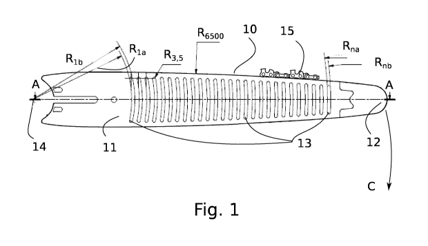
[0010] FIGURE 1 illustrates a side view of a guide bar in accordance
with at least some
embodiments of the present invention;
[0011] FIGURE 2A ¨ 2C illustrates exemplary cross- sections in the
plane A-A of FIG. 1
in accordance with at least some embodiments of the present invention;

CA 03100717 2020-05-27
WO 2019/110866 3
PCT/F12017/050858
[0012] FIGURE 3 illustrates an apparatus for operating a chain saw in
a forestry machine
in accordance with at least some embodiments of the present invention.
EMBODIMENTS
[0013] Definitions
[0014] Furrowed/furrow - is a term similar to corrugated, but is used in
the disclosure to
cover the situation where the surfaces of the guide bar may have either only
indentations or only
ridges, and to cover cases where the alternating structures, i.e. indentations
vs. plane surface,
ridges vs. plane surface, or indentations vs. ridges, are not necessarily
mutually symmetrical in
any way (as in corrugation), but may have a different shape, width, depth and
so on.
[0015] FIG. 1 shows an inventive guide bar 10 for a chain saw, comprising
two opposite
elongate surfaces 11. A slot (see Fig. 2s 2A ¨ 2C) is formed between the
opposite sides and is
running along the periphery of the guide bar and which receives the chain 15
(not in exact scale
and only a section shown). At the end 12 of the guide bar there may be a
lubricated sprocket
wheel in the slot, for supporting and guiding the chain. According to the
invention, at least one
of the elongate surfaces 11 is furrowed 13 across its surface in the direction
C of the cutting
movement of the guide bar 10.
[0016] According to some embodiments, see FIG. 2A, the furrow is
provided by
indentations 22 in both the opposite surfaces 21 of the elongate bar guide
20a, enclosing between
them a slot 23 for the chain.
[0017] According to some embodiments, see FIG. 2B, the furrow is provided
by ridges 24
on both the opposite surfaces 25 of the elongate bar guide 20b, enclosing
between them a slot 23
for the chain.
[0018] According to some embodiments, see FIG. 2C, the furrow is
provided by alternate
indentations 26 and ridges 27 in both the opposite surfaces of the elongate
bar guide 20c,
enclosing between them a slot 23 for the chain.
[0019] According to some embodiments, the furrow 13 across the surface
11 of the guide
bar 10 is formed as a section of the periphery of a circle, thus having a
radius. According to one
useful embodiment, each indentation and/or ridge with their radiuses Ria, Rib
¨ Rna , Rob, forms a

CA 03100717 2020-05-27
WO 2019/110866 4
PCT/F12017/050858
sector of a respective circle having its centre at the pivot or fastening
point 14 at the equipment
end of the guide bar.
[0020] The number (n) of indentations and/or ridges on the guide bar
10 may vary
considerably, depending on the equipment (speed, lubrication, guide bar
material etc.), the
material (wood hardness etc.) to be sawed, and/or on outer circumstances, such
as humidity.
[0021] In FIG. 3 is shown an exemplary apparatus 30 for operating a
chain saw in a
forestry machine. The apparatus comprises an engine or hydraulic power unit
32to drive the
chain (not shown) on the guide bar 31, which is furrowed 36 as described
above. The guide bar
31 is pivoted with a mechanism 33 in order to move the guide bar in a cutting
direction. The
apparatus 30 further comprise roller means 34 for forwarding the log (not
shown) to a cutting
position and clamping means 35 for keeping the log in position.
[0022] It is to be understood that the embodiments of the invention
disclosed are not
limited to the particular structures, process steps, or materials disclosed
herein, but are extended
to equivalents thereof as would be recognized by those ordinarily skilled in
the relevant arts. It
should also be understood that terminology employed herein is used for the
purpose of
describing particular embodiments only and is not intended to be limiting.
[0023] Furthermore, the described features, structures, or
characteristics may be combined
in any suitable manner in one or more embodiments. In the description,
numerous specific
details are provided, such as examples of lengths, widths, shapes, etc., to
provide a thorough
understanding of embodiments of the invention. One skilled in the relevant art
will recognize,
however, that the invention can be practiced without one or more of the
specific details, or with
other methods, components, materials, etc. In other instances, well-known
structures, materials,
or operations are not shown or described in detail to avoid obscuring aspects
of the invention.
[0024] For example, the concept of a chain saw should be interpreted
to encompass all
types of saws having a guide bar and a chain, independently of the type of the
chain drive and
the purpose of the saw. Also the guide bar is to be interpreted to cover all
guide bars carrying a
chain, i.e. also guide bars with special functions, such as stump pesticide
(e.g. urea) treatment
guide bars.
[0025] While the forgoing examples are illustrative of the principles
of the present
invention in one or more particular applications, it will be apparent to those
of ordinary skill in
the art that numerous modifications in form, usage and details of
implementation can be made

CA 03100717 2020-05-27
WO 2019/110866 5 PCT/F12017/050858
without the exercise of inventive faculty, and without departing from the
principles and concepts
of the invention. Accordingly, it is not intended that the invention be
limited, except as by the
claims set forth below.

Dessin représentatif
Une figure unique qui représente un dessin illustrant l'invention.
États administratifs

Pour une meilleure compréhension de l'état de la demande ou brevet qui figure sur cette page, la rubrique Mise en garde , et les descriptions de Brevet , États administratifs , Taxes périodiques et Historique des paiements devraient être consultées.

États administratifs

Titre Date
Date de délivrance prévu Non disponible
(86) Date de dépôt PCT 2017-12-04
(87) Date de publication PCT 2019-06-13
(85) Entrée nationale 2020-05-27
Requête d'examen 2022-11-02

Historique d'abandonnement

Il n'y a pas d'historique d'abandonnement

Taxes périodiques

Dernier paiement au montant de 210,51 $ a été reçu le 2023-11-28


 Montants des taxes pour le maintien en état à venir

Description Date Montant
Prochain paiement si taxe applicable aux petites entités 2024-12-04 100,00 $
Prochain paiement si taxe générale 2024-12-04 277,00 $

Avis : Si le paiement en totalité n'a pas été reçu au plus tard à la date indiquée, une taxe supplémentaire peut être imposée, soit une des taxes suivantes :

  • taxe de rétablissement ;
  • taxe pour paiement en souffrance ; ou
  • taxe additionnelle pour le renversement d'une péremption réputée.

Les taxes sur les brevets sont ajustées au 1er janvier de chaque année. Les montants ci-dessus sont les montants actuels s'ils sont reçus au plus tard le 31 décembre de l'année en cours.
Veuillez vous référer à la page web des taxes sur les brevets de l'OPIC pour voir tous les montants actuels des taxes.

Historique des paiements

Type de taxes Anniversaire Échéance Montant payé Date payée
Taxe de maintien en état - Demande - nouvelle loi 2 2019-12-04 100,00 $ 2020-05-27
Le dépôt d'une demande de brevet 2020-05-27 400,00 $ 2020-05-27
Taxe de maintien en état - Demande - nouvelle loi 3 2020-12-04 100,00 $ 2020-12-03
Taxe de maintien en état - Demande - nouvelle loi 4 2021-12-06 100,00 $ 2022-05-23
Surtaxe pour omission de payer taxe de maintien en état pour demande 2022-05-24 150,00 $ 2022-05-23
Enregistrement de documents 2022-09-06 100,00 $ 2022-09-06
Requête d'examen 2022-12-05 816,00 $ 2022-11-02
Taxe de maintien en état - Demande - nouvelle loi 5 2022-12-05 203,59 $ 2022-11-21
Taxe de maintien en état - Demande - nouvelle loi 6 2023-12-04 210,51 $ 2023-11-28
Titulaires au dossier

Les titulaires actuels et antérieures au dossier sont affichés en ordre alphabétique.

Titulaires actuels au dossier
LE HOLDING OU
Titulaires antérieures au dossier
FOMATEC OY
Les propriétaires antérieurs qui ne figurent pas dans la liste des « Propriétaires au dossier » apparaîtront dans d'autres documents au dossier.
Documents

Pour visionner les fichiers sélectionnés, entrer le code reCAPTCHA :


Pour visualiser une image, cliquer sur un lien dans la colonne description du document. Pour télécharger l'image (les images), cliquer l'une ou plusieurs cases à cocher dans la première colonne et ensuite cliquer sur le bouton "Télécharger sélection en format PDF (archive Zip)" ou le bouton "Télécharger sélection (en un fichier PDF fusionné)".

Liste des documents de brevet publiés et non publiés sur la BDBC .

Si vous avez des difficultés à accéder au contenu, veuillez communiquer avec le Centre de services à la clientèle au 1-866-997-1936, ou envoyer un courriel au Centre de service à la clientèle de l'OPIC.


Description du
Document 
Date
(yyyy-mm-dd) 
Nombre de pages   Taille de l'image (Ko) 
Abrégé 2020-05-27 1 59
Revendications 2020-05-27 2 69
Dessins 2020-05-27 2 148
Description 2020-05-27 5 211
Dessins représentatifs 2020-05-27 1 17
Traité de coopération en matière de brevets (PCT) 2020-05-27 3 107
Rapport de recherche internationale 2020-05-27 11 386
Demande d'entrée en phase nationale 2020-05-27 8 299
Paiement de taxe périodique 2020-12-03 1 33
Correspondance reliée au PCT 2020-11-25 8 364
Page couverture 2020-12-18 1 41
Requête d'examen 2022-11-02 4 152
Demande d'examen 2024-04-09 5 270
Paiement de taxe périodique 2023-11-28 1 33