Note : Les descriptions sont présentées dans la langue officielle dans laquelle elles ont été soumises.
CA 03126827 2021-07-14
WO 2020/150176
PCT/US2020/013420
ADJUSTABLE DOSE DRUG DELIVERY SYSTEM
CROSS-REFERENCE TO RELATED APPLICATIONS
This application claims the benefit of U.S. Provisional Application No.
62/792,972. filed January
16, 2019, and incorporated by reference herein in its entirety.
BACKGROUND OF THE INVENTION
(1) Field of the Invention
The present application generally relates to drug administration systems. More
specifically, systems having an adjustable dose mechanism allowing setting and
locking the dose
then administration of the set dose.
(2) Description of the related art
A system for home administration of a drug has several preferred
characteristics. The
system should have simple, foolproof procedures for administering the drug.
The system also
preferably has a dosage adjustment mechanism that allows for the dosage to be
set depending on
the needs of the patient. The system can also have a mechanism allowing the
set dosage to be
locked, e.g., by a pharmacist. See US Patents 5,462,740; 5,578,011; 5,632,733;
6,090,077;
6,572,584; 7,329,241; and 7,351,224, and PCT Patent Publication WO
2018/085759.
Provided is a drug delivery system having the above characteristics.
BRIEF SUMMARY OF THE INVENTION
Provided is an adjustable dose drug delivery system. The system comprises
a plunger, a syringe body, an inner housing, an outer housing, a stop sleeve,
and a lock
collar, wherein
the plunger comprises a stopper at a plunger distal end, a plunger proximal
end, and a
plunger stem extending from the plunger distal end to the plunger proximal
end;
the syringe body comprises a cylinder, and further comprises a syringe tip at
a syringe body
distal end and an open syringe body proximal end,
wherein the plunger is slidably deposed by inserting the stopper into the open
proximal end of the syringe body and pushing the plunger flange toward the
syringe body distal
end;
-1-
CA 03126827 2021-07-14
WO 2020/150176
PCT/US2020/013420
the inner housing comprises a cylinder, and further comprises an inner housing
proximal
end and an inner housing distal end and substantially encloses the syringe
body and is affixed
thereto, wherein the inner housing further comprises
an upper flange below the engagement pits,
a lower flange between the upper flange and the inner housing distal end, with
an
inter-flange area between the upper flange and lower flange, and
an administration tip distal to the lower flange that is hollow and
accommodates, at
its proximal end, the syringe tip;
the outer housing comprises a cylinder that encompasses the inner housing from
above the
lower flange to above the mechanism that engages the stop sleeve, the outer
housing further
comprising an outer housing proximal end and an outer housing distal end,
wherein the outer
housing further comprises
an outer housing distal region adjacent to the inter-flange area of the inner
housing,
wherein the outer housing distal region
has a narrower circumference than the outer housing proximal end, and
comprises a lock collar actuating mechanism that, when engaged, prevents
rotation of the outer housing relative to the inner housing;
a dosage window displaying dosage information present on an outer surface of
the
stop sleeve; and
a stop sleeve engagement mechanism that engages the stop sleeve to prevent the
stop sleeve from further movement when a designated dosage is dispensed;
the stop sleeve comprises a cylinder with a stop sleeve proximal end and a
stop sleeve distal
end, wherein the stop sleeve is deposed between the outer housing and the
inner housing above
the upper flange, the stop sleeve further comprising
a mechanism that engages the stop sleeve engagement mechanism on the outer
housing, and
markings near the stop sleeve distal end indicating dosage settings; and
the lock collar encircles a portion of the outer housing distal region and
engages with the
lock collar actuating mechanism when the lock collar is slid toward the upper
flange.
Also provided is a method of administering a medicament using the above
adjustable dose
drug delivery system. The method comprises
- 2 -
CA 03126827 2021-07-14
WO 2020/150176
PCT/US2020/013420
hold the outer housing proximal to the outer housing distal region, grasp the
lower flange
and turn the lower flange relative to the outer housing until a desired dosage
is indicated in the
dosage window;
slide the lock collar toward the upper flange to engage the lock collar
actuating mechanism;
insert the administration tip into a bodily orifice of a patient in need of
the medicament;
dispense the medicament through the administration tip by pushing the plunger
toward the
syringe body distal end until the plunger cannot be pushed any further.
BRIEF DESCRIPTION OF THE DRAWINGS
In accordance with the present invention,
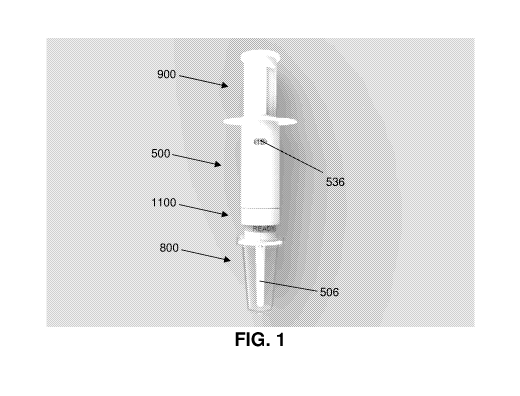
FIG. 1 is a perspective view of an adjustable dose drug delivery system.
FIG. 2 is an exploded view of an adjustable dose drug delivery system.
FIG. 3 is a transparent view of a plunger inserted into a syringe body.
FIG. 4 is a perspective view of a syringe body with plunger inserted therein
with an inner
housing.
FIG. 5 is a transparent view of a syringe body and plunger inside an inner
housing.
FIG. 6 is a transparent view of a syringe body and plunger inside an inner
housing with a
stop sleeve and snap top.
FIG. 7 is a transparent view of a syringe body, plunger, inner housing, stop
sleeve, snap
top and outer housing.
FIG. 8 is a transparent view of a syringe body, plunger, inner housing, stop
sleeve, snap
top and outer housing, with an exploded view of a lock collar.
FIG. 9 is a transparent view of a syringe body, plunger, inner housing, stop
sleeve, snap
top, outer housing and lock collar.
FIG. 10 is a transparent view of a syringe body, plunger, inner housing, stop
sleeve, snap
top, outer housing, lock collar and seal pin.
FIG. 11 is a transparent view of a syringe body, plunger, inner housing, stop
sleeve, snap
top, outer housing, lock collar and protective cap.
FIG. 12 is a close-up transparent view of the distal portion of an outer
housing and an inner
.. housing, with a lock collar, seal pin and protective cap.
FIG. 13 is a close-up view of the distal portion of an outer housing, with a
lock collar and
protective cap.
- 3 -
CA 03126827 2021-07-14
WO 2020/150176
PCT/US2020/013420
FIG. 14 is a perspective view of the inside of a half of an outer housing with
a lock collar
half.
FIG. 15 is a perspective view of the inside of a half of an outer housing with
a lock collar
half.
FIG. 16 is a perspective view of a protective cap, snap top, stop sleeve and
inner housing
with a cutaway of an outer housing.
FIG. 17 is a closeup of a stop sleeve, snap top and a portion of an inner
housing.
FIG. 18 is a closeup of a protective cap with a portion of the inside of an
outer housing
with a lock collar half.
FIG. 19 is a cutaway of an outer housing over an inner housing.
DETAILED DESCRIPTION OF THE INVENTION
As used herein, the singular forms "a", "an" and "the" are intended to include
the plural
forms as well, unless the context clearly indicates otherwise. Additionally,
the use of "or" is
intended to include "and/or", unless the context clearly indicates otherwise.
As used herein, "distal" is toward the end of the administrative tip;
"proximal" is toward
the portion of the plunger that is furthest from the stopper.
Provided is an adjustable dose drug delivery system. The system comprises
a plunger, a syringe body, an inner housing, an outer housing, a stop sleeve,
and a lock
collar, wherein
the plunger comprises a stopper at a plunger distal end, a plunger proximal
end, and a
plunger stem extending from the plunger distal end to the plunger proximal
end;
the syringe body comprises a cylinder, and further comprises a syringe tip at
a syringe body
distal end and an open syringe body proximal end comprising a syringe body
flange,
wherein the plunger is slidably deposed by inserting the stopper into the open
proximal end of the syringe body and pushing the plunger flange toward the
syringe body distal
end;
the inner housing comprises a cylinder, and further comprises an inner housing
proximal
end and an inner housing distal end and substantially encloses the syringe
body, wherein the inner
housing further comprises
- 4 -
CA 03126827 2021-07-14
WO 2020/150176
PCT/US2020/013420
an inner housing portion of a mechanism that engages the inner housing and
stop
sleeve to limit movement of the stop sleeve after the plunger is pushed toward
the syringe body
distal end in accordance with a dosage setting;
an upper flange below the mechanism that engages the inner housing and stop
sleeve,
a lower flange between the upper flange and the inner housing distal end, with
an
inter-flange area between the upper flange and lower flange, and
an administration tip distal to the lower flange that is hollow and
accommodates, at
its proximal end, the syringe tip;
the outer housing comprises a cylinder that encompasses the inner housing from
above the
lower flange to above the mechanism that engages the stop sleeve, the outer
housing further
comprising an outer housing proximal end and an outer housing distal end,
wherein the outer
housing further comprises
an outer housing distal region adjacent to the inter-flange area of the inner
housing,
wherein the outer housing distal region
has a narrower circumference than the outer housing proximal end, and
comprises a lock collar actuating mechanism that, when engaged, prevents
rotation of the outer housing relative to the inner housing;
a dosage window displaying dosage information present on an outer surface of
the
stop sleeve; and
a stop sleeve engagement mechanism that engages the stop sleeve to prevent the
stop sleeve from further movement when a designated dosage is dispensed;
the stop sleeve comprises a cylinder with a stop sleeve proximal end and a
stop sleeve distal
end, wherein the stop sleeve is deposed between the outer housing and the
inner housing above
the upper flange, the stop sleeve further comprising
a stop sleeve portion of a mechanism that engages the inner housing and stop
sleeve;
a mechanism that engages the stop sleeve engagement mechanism on the outer
housing, and
markings near the stop sleeve distal end indicating dosage settings; and
the lock collar encircles a portion of the outer housing distal region and
engages with the
lock collar actuating mechanism when the lock collar is slid toward the upper
flange.
- 5 -
CA 03126827 2021-07-14
WO 2020/150176
PCT/US2020/013420
Various nonlimiting embodiments of the system are depicted in the figures. One
such
embodiment is depicted in FIG. 1, showing a stop sleeve 900, an outer housing
500, a lock collar
1100, a protective cap 800 that protects an administration tip 506 when the
system is not in use,
and a dosage window 536.
An exploded illustration of the system, FIG. 2, reveals additional features
and relationships
between features. A snap top 1000 may be joined to a plunger 100 to provide
comfortable support
for a finger or thumb to administer a medicament by pushing the plunger toward
the distal end of
the inside of a syringe body 200. In some embodiments, the snap top 1000 is
originally separated
from the plunger in order to slide the stop sleeve 900 over the plunger 100
during manufacture of
the system. In other embodiments, the snap top is integrated with the plunger
at manufacture. The
outer housing 500 envelops the inner housing 300, which has the administration
tip 506 at its distal
end, which may be covered with the protective cap 800. In various embodiments,
a channel
extending through the length of the administration tip 506, through which a
medicament is
administered, has a seal pin 1200 inserted therein when the system is not in
use. The distal region
of the outer housing 546 is enveloped by the lock collar 1100.
Where it may be convenient, any of the parts of the system may be manufactured
in parts
(e.g., in halves), as shown with the outer housing 500 and the lock collar
1100, which can be
assembled during production of the system.
FIG. 3 provides details of a plunger 100 and syringe body 200 featured in some
embodiments of the invention. The illustrated plunger 100 comprises a stopper
102 at its distal
end, a plunger stem 104, a plunger flange 204, and a cap connector 100. The
cap connector 100 is
designed to couple with a snap cap 1000 and rest on the plunger flange 204
when the snap cap
1000 is snapped onto the cap connector 100. The interior of the syringe body
200 can hold a
medicament before administration. The distal end of the syringe body 200 has a
syringe tip 202,
through which a substance (e.g., a medicament) in the syringe body 200 is
dispensed into the
administration tip 318 when the plunger 100 is pushed through the syringe body
200. The proximal
end of the syringe body 200 has a syringe body flange 204, and a syringe body
tab 206. These
features engage the inner housing as described below.
The interaction of the syringe body 200 with the inner housing 300 is shown in
FIG. 4 and
FIG. 5. The illustrated embodiment shows an inner housing 300 having a lower
flange 324 with
lower flange indentations 334 that engages the protective cap 800 to retain
the protective cap 800
on the lower flange 324 to protect the administration tip 318. The inner
housing 300 also has an
- 6 -
CA 03126827 2021-07-14
WO 2020/150176
PCT/US2020/013420
upper flange 326, an inter-flange area 328, stop sleeve engagement rails 320
and a plurality of stop
sleeve engagement pits 330 that are circumferentially and vertically deposed
on the inner housing
between the inner housing proximal end and the inner housing distal end, above
the upper flange
326. The functions of these external portions of the inner housing 300 are
discussed below. The
syringe body 200, with a plunger 100 inserted therein, is deposed inside the
inner housing 326
such that the inner housing 326 substantially encloses the syringe body 200.
In the illustrated embodiments, the syringe body 200 is inserted into the
inner housing 326
until an attachment tab 322 at the proximal end of the inner housing 300
engages a syringe body
tab 206 at the proximal end of the syringe body 200, joining the syringe body
200 with the inner
housing 300 such that the proximal end of the inner housing 300 abuts the
bottom of the syringe
body flange 204. There may be more than one (e.g., 2, 3 or 4) syringe body tab
206 and attachment
tab 322.
FIG. 6 shows the relationship of the inner housing 300 with the stop sleeve
900 in the
illustrated embodiment. The stop sleeve 900 includes stop sleeve slots 906
comprising indentations
in the stop sleeve, the stop sleeve slots 906 deposed at the stop sleeve
distal end and extending
toward the stop sleeve proximal end for varying distances depending on a
specific dosage
corresponding to each stop sleeve slot (further discussed below) 906, and stop
sleeve tongues 908,
at the end of each stop sleeve slot 906. The stop sleeve tongue 908 has an
inner knob 916 protruding
inside of a distal end of the stop sleeve tongue 908 that engages the
engagement pits 330 when the
plunger 100 and stop sleeve 900 are pushed distally, limiting movement of the
stop sleeve 900
toward the inner housing 300 proximal end. In some embodiments, the stop
sleeve tongue 908 and
engagement pits 330 are not present.
The stop sleeve 900 also has inner housing engagement guides 910 that engage
the elevated
stop sleeve engagement rails 320 to join the inner housing 300 with the stop
sleeve 900 to rotate
together. There may be more than one (e.g., 2, 3, or 4) set of inner housing
engagement guides 910
and stop sleeve engagement rails 320 circumferentially deposed on the stop
sleeve 900 and inner
housing 300.
The outer housing 500 and its relationship to the stop sleeve 900 and inner
housing 300 is
shown in FIG. 7. In the illustrated embodiment, the distal end of the outer
housing 544 rests on the
lower flange of the inner housing 324. The outer housing distal region 546 is
indented, forming an
outer housing ridge 522 on its proximal edge, and comprises at least one outer
housing flap 514
comprising a lock collar engagement tab 516, a lock collar guide rail 518,
which are components
- 7 -
CA 03126827 2021-07-14
WO 2020/150176
PCT/US2020/013420
that engage the lock collar 1100. The illustrated outer housing has an outer
housing flange 524 at
its proximal end, which provides a finger hold when a medicament is
administered by pushing on
the snap top 1000 in a distal direction, which also moves the stop sleeve 900,
and the plunger 100
distally. In some embodiments, a stop sleeve tongue 908 and engagement pits
330 are present. In
those embodiments, the stop sleeve tongue 908 sequentially engages the
engagement pits 330
through its inner knob 916, preventing proximal movement of the stop sleeve
900, and the plunger
100 and snap top 1000 joined thereto.
FIG. 8 and FIG. 9 show the lock collar 1100 of the illustrated embodiment, and
its
engagement with the outer housing distal region 546. The lock collar 1100 can
be manufactured
in halves 1102, which are joined during assembly of the system. In some
embodiments, the lock
collar halves 1102 have lock collar assembly pegs 1104 which are inserted into
lock collar
assembly holes 1106 during assembly. Before use, the lock collar 1100
encircles the distal portion
of the outer housing distal region 546. After the dosage is set, by turning
the outer housing 500
relative to the stop sleeve 900 until the designated dosage, as indicated by
the dosage marking 912
on a distal portion of the stop sleeve 900, as shown in FIG. 17, appears in
the dosage window 536
of the outer housing 500, as shown in FIG. 14, the dosage setting is locked by
sliding the lock
collar 1100 to the outer housing ridge 522 until a lock collar upper shelf
1108, on the inside of the
lock collar 1100 engages the lock collar engagement tab 516 on the outer
housing flap 514. The
lock collar lower shelf 1110, distal to the lock collar upper shelf 1108, then
rests on the lock collar
guide rail 518 on the outer housing 500. When the lock collar 1100 is so
engaged, a lock collar
engagement tab 516 on the inside of the outer housing 500, as shown in FIG.
14, is pushed inwardly
to cause the outer housing flap inner tab 526, as shown in FIGS. 12, 14, and
15, to interfere with
the rotation of the outer housing 500 relative to the inner housing 300 by
entering a gap in the
dosage lock railing 336 of the inner housing 300, as shown in FIG. 16 and FIG.
19.
FIG. 10 and FIG. 11 illustrate aspects of the distal portion of an embodiment
of the system,
showing the seal pin top 1202 at the dispensing hole 332 at the distal point
of the administration
tip 318. The lower flange 324 has indentations 334 that match indentations 808
in the cap
connector 806 at the proximal end of the protective cap 802, such that the
protective cap 800 stays
on the lower flange 324 until manually removed.
FIG. 12 shows the distal portion of the system in transparent view before
engaging the lock
collar 1100, further showing the relationship between various parts, including
the upper flange
326, the lower flange 324, the lock collar engagement tab 516, the outer
housing flap inner tab
- 8 -
CA 03126827 2021-07-14
WO 2020/150176
PCT/US2020/013420
526, the lock collar upper shelf 1108, the lock collar lower shelf 1110, the
protective cap 800, the
cap connector 806, the syringe tip 202, the administration tip 318, the
dispensing hole 332, the seal
pin top 1202, and the seal pin stem 1204.
The distal portion of the system after the lock collar 1100 is engaged is
shown in FIG. 13,
showing, inter alia, the protective cap 800, with its cap connector 806 and
cap connector
indentations 808.
FIG. 14 and FIG. 15 show two halves of the outer housing 500, outer housing
half A 528,
and outer housing half B 530. The outer housing 500 may be constructed in
parts, e.g., halves, as
illustrated, for example with assembly holds 532 and assembly pegs 534 and
outer housing
assembly alignment ridges 540, the latter feature used to ultrasonically
"weld" the two outer
housing halves 528, 530 together. The outer housing rotation tabs 520
interacts with the inner
housing rotation tab 340, shown in FIG. 16, to allow the inner housing 300 to
turn 180 degrees to
set the doses.
The dosage setting mechanism is shown in FIG. 14, FIG. 15 and FIG. 16, the
latter figure
showing the system with part of the outer housing 500 omitted. As previously
discussed, the
dosage is set by turning the outer housing 500 relative to the stop sleeve 900
until the designated
dosage, as indicated by the dosage marking 912 on a distal portion of the stop
sleeve 900, as shown
in FIG. 17, appears in the dosage window 536 of the outer housing half A 528.
This aligns the stop
sleeve slot 906 corresponding to the set dosage with the stop sleeve slot
engagement ridge 538 on
outer housing half B 530. When the plunger 100 is pushed distally along with
the stop sleeve 900,
the stop sleeve 900 travels along the inside of the outer housing 500, the
stop sleeve slot 906
corresponding to the set dosage traveling along outer housing half B 530 until
the stop sleeve slot
proximal end 914 abuts against the stop sleeve slot engagement ridge 538,
preventing further distal
movement, and causing the administration of the precise dosage that was set. A
closeup view of
relevant features at the proximal portion of the system is shown in FIG. 17,
including the dosage
marking 912 on the stop sleeve, and the stop sleeve slot proximal end 914. The
stop sleeve tongue
908, the stop sleeve tongue inner knob 916 and the stop sleeve tongue
engagement pits 330 are
also shown, which are present in some embodiments, and prevent movement of the
plunger 100
and stop sleeve 900 in the proximal direction, as previously discussed.
Additional views of various features of the illustrated embodiments described
above are
shown in FIG. 18 and FIG. 19.
- 9 -
CA 03126827 2021-07-14
WO 2020/150176
PCT/US2020/013420
Although the illustrated embodiments provide for a long administration tip
318, which is
particularly suitable for rectal administration, the system of the present
invention is also suitable
to be used with needles, where a needle is utilized instead of the
administration tip 318. The needle
could be used for any administration that uses a needle, e.g., intravenous,
subdermal,
intramuscular, intraperitoneal, etc., as those administration means are known
in the art.
In certain specific embodiments, the drug delivery system has an
administration tip suitable
for rectal administration, e.g., administration tip 318, and the drug is a
benzodiazepine, for example
diazepam. Such a system is suitable for treatment of, e.g., epilepsy.
Also provided is a method of administering a medicament using the above
adjustable dose
drug delivery system. The method comprises
hold the outer housing proximal to the outer housing distal region, grasp the
lower flange
and turn the lower flange relative to the outer housing until a desired dosage
is indicated in the
dosage window;
slide the lock collar toward the upper flange to engage the lock collar
actuating mechanism;
insert the administration tip into a bodily orifice of a patient in need of
the medicament;
dispense the medicament through the administration tip by pushing the plunger
toward the
syringe body distal end until the plunger cannot be pushed any further.
In some of these embodiments, the method further comprises
after dispensing the medicament,
pull the plunger in a proximal direction until the plunger is removed from the
syringe body;
replace the plunger into the syringe body and push the plunger toward the
syringe body
distal end until all of the medicament is dispensed through the administration
tip.
In some of these methods, the medicament is benzodiazepine and the bodily
orifice is a
rectal opening.
In certain of these embodiments, the turning of the lower flange relative to
the outer
housing and the sliding of the lock collar toward the upper flange is
performed by a pharmacist
who is not the patient.
In additional embodiments of these methods, the adjustable dose drug delivery
system
further comprises the seal pin inserted into the administration tip and the
protective cap,
the lower flange is grasped and turned by grasping and turning the
administration tip, and
the protective cap and the seal pin is removed before the administration tip
is inserted into
a bodily orifice of the patient.
- 10 -
CA 03126827 2021-07-14
WO 2020/150176
PCT/US2020/013420
In specific embodiments as illustrated in the figures, an adjustable dose drug
delivery
system is provided. The system comprises
a plunger, a syringe body, an inner housing, an outer housing, a stop sleeve,
a lock collar,
a seal pin, and a protective cap, wherein
the plunger comprises a stopper at a plunger distal end, a plunger proximal
end, and a
plunger stem extending from the plunger distal end to the plunger proximal
end, the plunger
proximal end further comprises a cap connector and a snap top, wherein
the snap top is a disk with a central fastener that joins with the cap
connector to
affix the snap top to the plunger proximal end;
the syringe body comprises a cylinder, and further comprises a syringe tip at
a syringe body
distal end and an open syringe body proximal end comprising a syringe body
flange,
wherein the plunger is slidably deposed by inserting the stopper into the open
proximal end of the syringe body and pushing the plunger flange toward the
syringe body distal
end;
the inner housing comprises a cylinder, and further comprises an inner housing
proximal
end and an inner housing distal end and encloses the syringe body and is
affixed thereto, wherein
the inner housing further comprises
an upper flange below the engagement pits,
a lower flange between the upper flange and the inner housing distal end, with
an
inter-flange area between the upper flange and lower flange, and
an administration tip distal to the lower flange that is hollow and
accommodates, at
its proximal end, the syringe tip;
the outer housing comprises a cylinder that encompasses the inner housing from
above the
lower flange to above the mechanism that engages the stop sleeve, the outer
housing further
comprising an outer housing proximal end, an outer housing distal end, wherein
the outer housing
further comprises
an outer housing distal region adjacent to the inter-flange area of the inner
housing,
wherein the outer housing distal region
has a narrower circumference than the outer housing proximal end, and
comprises a lock collar actuating mechanism that, when engaged, prevents
rotation of the outer housing relative to the inner housing;
-11-
CA 03126827 2021-07-14
WO 2020/150176
PCT/US2020/013420
a dosage window displaying dosage information present on an outer surface of
the
stop sleeve; and
the stop sleeve comprises a cylinder with a stop sleeve proximal end and a
stop sleeve distal end, wherein the stop sleeve is deposed between the outer
housing and the inner
housing above the upper flange,
the stop sleeve further comprising
markings near the stop sleeve distal end indicating dosage settings;
a plurality of stop sleeve slots comprising indentations in the stop sleeve,
the stop
sleeve slots deposed at the stop sleeve distal end and extending toward the
stop sleeve proximal
end for varying distances depending on a specific dosage corresponding to each
stop sleeve slot;
and
a stop sleeve slot engagement ridge protruding from an inside surface of the
outer
housing, wherein the stop sleeve slot engagement ridge engages with a stop
sleeve slot proximal
end to limit movement of the stop sleeve and attached plunger in accordance
with the dosage
setting;
the lock collar encircles a portion of the outer housing distal region and
engages with the
lock collar actuating mechanism when the lock collar is slid toward the upper
flange,
wherein the lock collar actuating mechanism comprises
an outer housing flap in the outer housing distal region, the outer housing
flap
further comprising (a) a lock collar engagement tab the protrudes outward on
the outer housing
flap, and (b) an outer housing flap inner tab protruding from an inside
surface of the outer housing
flap;
a lock collar upper shelf comprising a ledge protruding from an inside of the
lock
collar on a proximal area of the lock collar; and
a dosage lock railing comprising a ledge protruding from a proximal area of
the
inter-flange area of the inner housing, wherein the dosage lock railing has a
gap that accommodates
the outer housing flap inner tab, wherein
when the lock collar is slid toward the upper flange, the ledge of the lock
collar
upper shelf pushes the lock collar engagement tab, directing the outer housing
flap inwardly, which
causes the outer housing flap inner tab to enter the gap in the dosage lock
railing, preventing
rotation of the outer housing relative to the inner housing;
the seal pin comprises
- 12 -
CA 03126827 2021-07-14
WO 2020/150176
PCT/US2020/013420
a seal pin stem comprising a long, thin needle that can be inserted into the
administration tip hollow portion through a dispensing hole at a distal end of
the administration
tip; and
a seal pin top at a distal end of the seal pin stem, wherein the seal pin top
prevents
complete insertion of the seal pin into the administration tip; and
the protective cap encloses the administration tip and is affixed to the lower
flange,
the adjustable dose drug delivery system further comprising:
components joining the inner housing and the stop sleeve to rotate together,
comprising
a stop sleeve engagement rail comprising an elevated rail on the inner housing
that
substantially extends from the inner housing upper flange to the inner housing
proximal end; and
an inner housing engagement guide comprising a protruding area at the stop
sleeve
distal end that accommodates the stop sleeve engagement rail;
a lock collar lower shelf comprising a ledge protruding from an inside of the
lock collar on
a distal area of the lock collar; and
a lock collar guide rail comprising a ledge in the outer housing distal
region, wherein
the lock collar lower shelf rests on the lock collar guide rail prior to
engagement of the lock
collar actuating mechanism,
wherein
the dosage is set by turning the outer housing relative to the stop sleeve,
inner housing,
syringe body and plunger until a desired dosage marked on the stop sleeve is
indicated in the
dosage window;
the dosage setting is locked by sliding the lock collar toward the upper
flange until the lock
collar actuating mechanism is engaged; and
the set dosage of a substance present in the syringe body is expelled through
a dispensing
hole at a distal end of the administration tip.
Also provided is a method of administering a medicament using the adjustable
dose drug
delivery system as described immediately above and as illustrated in the
figures. The method
comprises
hold the outer housing proximal to the outer housing distal region, grasp the
protective cap
and turn the protective cap relative to the outer housing until a desired
dosage is indicated in the
dosage window;
- 13 -
CA 03126827 2021-07-14
WO 2020/150176
PCT/US2020/013420
slide the lock collar toward the upper flange to engage the lock collar
actuating mechanism;
remove (a) the protective cap from the lower flange, and (b) the seal pin from
the
administration tip;
insert the administration tip into a bodily orifice of a patient in need of
the medicament;
and
dispense the medicament through the administration tip by pushing the plunger
toward the
syringe body distal end until the plunger cannot be pushed any further.
In various embodiments, the method further comprises, after dispensing the
medicament,
pull the plunger in a proximal direction until the plunger is removed from the
syringe body;
and
replace the plunger into the syringe body and push plunger toward the syringe
body distal
end until all of the medicament is dispensed through the administration tip.
In certain embodiments of this method, the medicament is benzodiazepine and
the bodily
orifice is a rectal opening.
In other embodiments, the turning of the protective cap relative to the outer
housing and
the sliding of the lock collar toward the upper flange is performed by a
pharmacist who is not the
patient.
In view of the above, it will be seen that several objectives of the invention
are achieved
and other advantages attained.
As various changes could be made in the above methods and compositions without
departing from the scope of the invention, it is intended that all matter
contained in the above
description and shown in the accompanying drawings shall be interpreted as
illustrative and not in
a limiting sense.
All references cited in this specification are hereby incorporated by
reference. The
discussion of the references herein is intended merely to summarize the
assertions made by the
authors and no admission is made that any reference constitutes prior art.
Applicants reserve the
right to challenge the accuracy and pertinence of the cited references.
- 14 -