Note : Les descriptions sont présentées dans la langue officielle dans laquelle elles ont été soumises.
CA 03128394 2021-07-30
1
Attorney Ref.: 1052P012CA01
MECHANICAL FACE SEAL ASSEMBLY SUITABLE FOR PRESSURE
REVERSAL
Field of Invention
The present invention relates to a mechanical seal arrangement that is
suitable for providing
appropriate sealing even when reversing pressure.
Background
Mechanical seals are known from prior art in various configurations. During
operation, situations may
occur where pressure conditions at the mechanical seal arrangement are
reversed, for example due
to incorrect operation or failure of or damage to components. In such a
situation, the mechanical
seal arrangement is required to ensure minimal or no leakage even in the event
of pressure reversal,
since otherwise corresponding damage or environmental pollution could occur,
for example when
sealing toxic media or media that are harmful to humans and the environment.
For this purpose,
mechanical seal arrangements with improved secondary sealing elements are
used, for example,
as known from DE10 2012 022 465 Al. However, they are usually very expensive
secondary sealing
elements, which make the mechanical seal arrangement correspondingly more
expensive in terms
of cost.
Summary
Therefore, it is the object of the present invention to provide a mechanical
seal arrangement which,
with a simple and inexpensive design, withstands especially a pressure
reversal and, if possible,
prevents leakage at the mechanical seal during pressure reversal.
This object will be solved by a mechanical seal arrangement having the
features described herein.
The mechanical seal arrangement according to the invention ensures reliable
sealing to be possible
even when reversing pressure conditions at the mechanical seal arrangement. It
is possible to use
standard components, so that the mechanical seal arrangement can be provided
at particularly low
cost. For this purpose, the mechanical seal arrangement comprises a mechanical
seal including a
rotating slide ring and a stationary slide ring, which define a sealing gap
between their sealing
surfaces. Furthermore, a pretensioning device is provided which is used to
pretension the stationary
slide ring against the rotating slide ring in the axial direction of the
mechanical seal arrangement.
Furthermore, the mechanical seal arrangement comprises a support ring which is
arranged on the
stationary slide ring and which is movable in the axial direction in relation
to the stationary slide ring,
the pretensioning device being arranged between the axially movable support
ring and the stationary
slide ring. Furthermore, a fixing device is provided, which is arranged to fix
the support ring in axial
Date Revue/Date Received 2021-07-30
CA 03128394 2021-07-30
2
Attorney Ref.: 1052P012CA01
direction to a stationary component to be axially movable. Furthermore, a stop
is provided which
limits a first travel distance by which the axially movable support ring can
axially be moved, as well
as a secondary seal, which is configured for sealing between the support ring
and the stationary
component. When pressure reversal occurs, the support ring is subjected to a
higher pressure from
the other axial side than during regular operation, so that the support ring
will be moved towards the
stationary slide ring. This increases a spring force of the pretensioning
device on the stationary slide
ring so that consistent sealing is ensured at the sealing gap between the
rotating and stationary slide
rings.
Preferably, the fixing device comprises a plurality of bolts, and the support
ring comprises a plurality
of recesses through which the bolts are passed. Simple and safe axial
movability of the support ring
may thereby be achieved. Preferably, the recesses are provided on the outer
circumference of the
support ring. Particularly preferably, the recesses are provided as
semicircles or as semi-ovals.
A particularly easy structure results if the stop comprises at least one
retaining ring, which is arranged
on at least one of the bolts to limit axial travel of the support ring. The
retaining ring may be fixed to
the bolt or alternatively a shoulder may be provided on the bolt instead of
the retaining ring.
According to an alternative embodiment of the invention, the fixing device
comprises a plurality of
.. headed bolts, the stop being provided by the head of the bolts.
Particularly preferably, the bolts are equally spaced along the circumference
of the support ring.
Further preferably, the support ring has a groove for receiving the secondary
seal. This allows
realization of a particularly solid structure. The groove in the support ring
also ensures the smallest
possible axial overall length of the mechanical seal arrangement. The groove
is provided on a side
of the support ring facing away from the stationary slide ring. Particularly
preferably, the groove is
arranged on a radial inner circumference of the support ring.
Alternatively, the support ring is groove-free and the secondary seal is
arranged on a stationary
component. In this case, it is particularly preferably to provide a groove for
the secondary seal in the
stationary component, where the secondary seal is arranged. The secondary seal
then seals against
the groove-free side of the support ring.
Particularly preferably, the secondary seal is an 0-ring or a quad ring. This
means that the secondary
seal can be provided with particular ease and at low cost.
Date Recue/Date Received 2021-07-30
Attorney Ref.: 1052P012CA01
3
Preferably, a second axial path is provided between the stationary component
and the
axially movable support ring. Herein, the first axial travel distance between
the support
ring and the stop is smaller than the second axial travel distance between the
support
ring and the stationary component when pressure reversal occurs. This means
that
reliable sealing of the secondary seal may always be ensured.
Further preferably, the pretensioning device comprises a plurality of springs,
which are
especially cylindrical springs. Particularly preferably, the springs are
arranged at equal
intervals along the circumference and are supported on the support ring.
Alternatively,
only one single spring element is provided.
Further preferably, the mechanical seal arrangement further comprises a
stationary slide
ring carrier holding the stationary slide ring, wherein the pretensioning
device is
arranged between the stationary slide ring carrier and the support ring. As a
result, the
pretensioning device is not in direct contact with the stationary slide ring,
so that
especially a material of the stationary slide ring may freely be selected.
In another aspect, this document discloses a mechanical seal arrangement
comprising:
a mechanical seal with a rotating slide ring and a stationary slide ring
having a sealing
gap defined therebetween, a pretensioning device which pretensions the
stationary slide
ring in the axial direction of the mechanical seal assembly, a support ring
which is
arranged on the stationary slide ring, the support ring being axially movable
in relation to
the stationary slide ring, the pretensioning device being arranged between the
support
ring and the stationary slide ring, a fixing device which is arranged for
axially movable
fixing the support ring to a stationary component, a stop which limits a first
travel
distance by which the axially movable support ring can be moved, and a
secondary seal,
which is arranged to seal between the support ring and the stationary
component.
In another aspect, this document discloses a mechanical seal arrangement
comprising:
a mechanical seal with a rotating slide ring and a stationary slide ring
having a sealing
gap defined therebetween, a pretensioning device which pretensions the
stationary slide
ring in the axial direction of the mechanical seal assembly, a support ring
which is
arranged on the stationary slide ring, the support ring being axially movable
in relation to
the stationary slide ring, the pretensioning device being arranged between the
support
ring and the stationary slide ring, a fixing device which is arranged for
axially movable
fixing the support ring to a stationary component, a stop which limits a first
travel
distance by which the axially movable support ring can be moved, and a
secondary seal,
Date Recue/Date Received 2022-12-30
Attorney Ref.: 1052P012CA01
3a
which is arranged to seal between the support ring and the stationary
component,
wherein the fixing device comprises a plurality of bolts and the support ring
comprises a
plurality of recesses through which said bolts are passed, and wherein the
stop
comprises a retaining ring arranged on one of the plurality of bolts to limit
the axial first
travel distance of the axially movable support ring.
Brief Description of Drawings
In the following, preferred embodiments of the invention will be described in
detail while
reference will be made to the accompanying drawing, wherein:
Fig. 1 is a schematic longitudinal sectional view of a mechanical seal
arrangement
according to a first embodiment of the invention,
Fig. 2 is a schematic, enlarged partial sectional view of the mechanical seal
arrangement
of Fig. 1, and
Date Recue/Date Received 2022-12-30
CA 03128394 2021-07-30
4
Attorney Ref.: 1052P012CA01
Fig. 3 is a schematic, enlarged partial sectional view of a mechanical seal
arrangement according to
a second embodiment of the invention.
Detailed Description
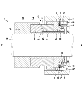
In the following, a mechanical seal arrangement 1 according to a first
preferred embodiment of the
invention will be described in detail, while making reference to Figs. 1 and
2.
As can be seen from Fig. 1, the mechanical seal arrangement 1 comprises a
mechanical seal 2 with
a rotating slide ring 3 and a stationary slide ring 4. A sealing gap 5 is
defined between the sliding
surfaces 3a, 4a of the slide rings 3, 4.
The mechanical seal arrangement seals a first space 15 against a second space
16 on a shaft 14.
A sleeve 13 is fixed to the shaft 14, which also holds the rotating slide ring
3. The stationary slide
ring 4 is axially movably connected to a stationary component 11 via a
stationary slide ring carrier
40.
The mechanical seal arrangement 1 further comprises a pretensioning device 6.
The pretensioning
device 6 comprises a plurality of cylindrical springs 60, which are arranged
at equal intervals along
the circumference.
Furthermore, the mechanical seal arrangement 1 comprises a support ring 7. The
support ring 7 is
arranged on the stationary slide ring 4 and is held to be axially movable,
which is indicated by the
double arrow A. The support ring 7 is arranged on the stationary slide ring 4.
That is, the support
ring 7 is movable in both directions of the axial direction X-X of the
mechanical seal arrangement 1.
The pretensioning device 6 including the plurality of cylindrical springs 60
is thereby arranged
between the support ring 7 and the stationary mechanical seal carrier 40.
Furthermore, a fixing device 8 is provided, which is configured to fix the
support ring 7 to the
stationary component 11 to be axially movable in relation to the stationary
slide ring 4. As can be
seen from Fig. 1, the fixing device 8 comprises a plurality of bolts 80 and
80'. The bolts 80' fix the
stationary mechanical seal carrier 40 to the stationary component 11. The
bolts 80 hold the support
ring 7 axially movably on the stationary component 11. The bolts 80, 80' are
each arranged in
recesses 71 on the outer circumference of the support ring 7.
Furthermore, the mechanical seal arrangement 1 comprises a stop 9. The stop 9
serves to limit the
axially travelable distance of the support ring 7. In this example embodiment,
the stop 9 is provided
on the fixing device 8. As can especially be seen from Fig. 2, herein, a
retaining ring 81 is arranged
Date Revue/Date Received 2021-07-30
CA 03128394 2021-07-30
Attorney Ref.: 1052P012CA01
on the bolt 80, which projects over the cylindrical outer circumference of the
bolt 80. The bolt contacts
the retaining ring 81 during axial movement of the support ring 7 towards the
stationary slide ring
carrier 40 thus limiting a first axial travel distance W1 towards the
stationary slide ring 4. A second
axial travel distance W2 towards the stationary component 11 is limited by the
stationary component
5 11 itself.
Fig. 2 shows the two travel distances W1, W2 in the regular operating state of
the mechanical seal
arrangement 1, wherein the travel distances are preferably equal.
Furthermore, the mechanical seal arrangement 1 comprises a secondary seal 10
in the form of an
0-ring. As can be seen from Fig. 2, the secondary seal 10 is arranged in a
groove 70 in the support
ring 7. The groove 70 is formed on a side 72 facing away from the stationary
slide ring. By arranging
the secondary seal 10 on the side facing away from the stationary slide ring
4, the axial movability
of the support ring 7, especially towards the stationary slide ring 4, is not
impaired. As can be seen
.. from Fig. 2, which shows the state referred to as the regular operating
state, where a first pressure
P1 in the first chamber 15 is greater than a second pressure P2 in the second
chamber 16, the
secondary seal 10 seals against the stationary seal ring carrier 40, on the
support ring 7 and on the
stationary component 11. Thus, no fluid can enter the first chamber 15 from
the second chamber 16
through the secondary seal 10. Since the first pressure P1 is also present at
the rear side of the
stationary mechanical seal carrier 40, sealing at the sealing gap 5 may
reliably be realized using the
pretensioning device 6.
In the event of a pressure reversal, when the second pressure P2 becomes
greater than the first
pressure P1, a pressure force F, starting from the second chamber 16, is
exerted on the secondary
.. seal 10. This is shown in Fig. 2 by the arrow F. As soon as the pressure
force F becomes greater
than the restoring force of the cylinder springs 60, the support ring 7 moves
toward the stationary
slide ring 4. This axial movement is limited by the retaining ring 81. This
ensures that the secondary
seal 10 is still attached to the stationary sealing surface 40, on the support
ring 7 and on the
stationary component 11, since a gap 17 between the support ring 7 and the
stationary component
11 does not become too large. Furthermore, sufficient closing force can also
be applied to the sealing
gap 5 at the sealing surfaces 3a, 4a of the slide rings 3, 4, so that the
slide ring seal 2 also keeps
sealing against the sealing surfaces 3a, 4a when the pressure is reversed.
This ensures only
minimum amount of fluid to pass from the second chamber 16 into the first
chamber 15 during
pressure reversal.
Fig. 3 shows a section of a mechanical seal arrangement according to a second
example
embodiment of the invention. The second embodiment is substantially the same
as the first
embodiment, with operationally equal parts being designated as in the first
embodiment.
Date Revue/Date Received 2021-07-30
CA 03128394 2021-07-30
6
Attorney Ref.: 1052P012CA01
As can be seen from Fig. 3, the support ring 7 is groove-free, in the second
example embodiment.
Herein, the secondary seal 10 is arranged in a groove 111 in the stationary
component 11. The
secondary seal seals against the side 72 of the support ring 7. In this way,
the support ring 7 can
particularly easily be manufactured. When the pressure conditions at the
mechanical seal
arrangement 1 are reversed, a compressive force F is applied to the secondary
seal 10, as in the
first embodiment. This allows the support ring 7 to move in the axial
direction X-X as far as the stop
9 on the retaining ring 81. In this case, however, the secondary seal 10
remains in sealing contact
with the stationary mechanical seal carrier 40, the support ring 7 and the
stationary component 11.
In this way, it is also possible to prevent large quantities of medium from
passing from the second
chamber 16 into the first chamber 15 when pressure reversal occurs at the
mechanical seal. At the
same time, the mechanical seal 2 also remains in the closed position.
As described in the example embodiments, a mechanical seal arrangement 1 may
thus be
provided in accordance with the invention, which enables reliable sealing
especially when pressure
reversal of the pressure conditions at the mechanical seal 2 occurs. As a
result, contamination of
the medium in chamber 15 by media from chamber 16, for example bearing oil,
can be minimized.
Date Recue/Date Received 2021-07-30
CA 03128394 2021-07-30
7
Attorney Ref.: 1052P012CA01
List of reference numbers
1 Mechanical seal arrangement
2 Mechanical seal
3 rotating slide ring
3a sliding surface
4 stationary slide ring
4a sealing surface
5 sealing gap
6 pretensioning device
7 support ring
8 fixing device
9 stop
10 secondary seal
11 stationary component
13 sleeve
14 shaft
15 first space
16 second space
17 gap
40 stationary mechanical seal
60 cylindrical spring
70 groove
71 recess for fixing device
72 side on support ring facing away from stationary slide ring
80, 80 bolt
81 retaining ring
111 groove
A axial movement of the support ring
pressure force at pressure reversal
P1 first pressure
P2 second pressure
W1 first travel distance of the support ring in axial direction to the
stationary slide ring
W2 second travel distance of the support ring in axial direction to the
stationary component
X-X axial direction
Date Recue/Date Received 2021-07-30