Sélection de la langue

Search

Sommaire du brevet 3136729 

Énoncé de désistement de responsabilité concernant l'information provenant de tiers

Une partie des informations de ce site Web a été fournie par des sources externes. Le gouvernement du Canada n'assume aucune responsabilité concernant la précision, l'actualité ou la fiabilité des informations fournies par les sources externes. Les utilisateurs qui désirent employer cette information devraient consulter directement la source des informations. Le contenu fourni par les sources externes n'est pas assujetti aux exigences sur les langues officielles, la protection des renseignements personnels et l'accessibilité.

Disponibilité de l'Abrégé et des Revendications

L'apparition de différences dans le texte et l'image des Revendications et de l'Abrégé dépend du moment auquel le document est publié. Les textes des Revendications et de l'Abrégé sont affichés :

  • lorsque la demande peut être examinée par le public;
  • lorsque le brevet est émis (délivrance).
(12) Demande de brevet: (11) CA 3136729
(54) Titre français: MECANISME D'ABAISSEMENT POUR OUTIL DE LEVAGE PORTATIF
(54) Titre anglais: LOWERING MECHANISM FOR HAND HELD JACKING TOOL
Statut: Examen demandé
Données bibliographiques
(51) Classification internationale des brevets (CIB):
  • B66F 1/02 (2006.01)
  • B65G 7/02 (2006.01)
  • E04F 21/18 (2006.01)
  • E04G 25/08 (2006.01)
(72) Inventeurs :
  • RESCH, OIVIND (Norvège)
(73) Titulaires :
  • VIKING ARM AS (Norvège)
(71) Demandeurs :
  • VIKING ARM AS (Norvège)
(74) Agent: MARKS & CLERK
(74) Co-agent:
(45) Délivré:
(86) Date de dépôt PCT: 2020-04-08
(87) Mise à la disponibilité du public: 2020-10-15
Requête d'examen: 2023-11-13
Licence disponible: S.O.
(25) Langue des documents déposés: Anglais

Traité de coopération en matière de brevets (PCT): Oui
(86) Numéro de la demande PCT: PCT/NO2020/050100
(87) Numéro de publication internationale PCT: WO2020/209731
(85) Entrée nationale: 2021-10-12

(30) Données de priorité de la demande:
Numéro de la demande Pays / territoire Date
20190508 Norvège 2019-04-12

Abrégés

Abrégé français

L'invention concerne un mécanisme d'abaissement pour un outil de levage portatif comprenant un mécanisme de levage de pistolet à calfeutrer. Le mécanisme d'abaissement comprend une plaque d'abaissement (4) au-dessus de la plaque de maintien (2), un levier de poussée (5) relié avec une fixation à charnière (6) à la plaque d'abaissement à une extrémité arrière, le levier de poussée étant pivotant autour d'une structure de pivot (8) reliée au levier ou à la plaque de maintien à une distance vers l'arrière de la fixation à charnière, amenant la plaque d'abaissement (4) à accrocher l'arbre de levage (3) lorsque le levier est poussé vers le bas puis, à son tour, pousser la plaque de maintien vers le bas et la desserrer de l'arbre de levage et la déplacer vers le bas le long de l'arbre de levage d'une distance déterminée par l'action de pivotement du levier. La plaque d'abaissement est maintenue en place par un ressort (9) sollicitant la plaque d'abaissement vers la plaque de maintien.


Abrégé anglais

Lowering mechanism for a hand held jacking tool comprising a caulking gun jacking mechanism. The lowering mechanism comprises a lowering plate (4) on top of the holding plate (2), a pushing lever (5) connected with a hinge attachment (6) to the lowering plate at a rear end, wherein the pushing lever is pivoting around a pivot structure (8) connected to the lever or holding plate a distance backward from the hinge attachment, causing the lowering plate (4) to grip the jacking shaft (3) when the lever is pushed downwards and then, in turn, pushing the holding plate downwards and loosening it from the jacking shaft and moving it down along the jacking shaft a distance determined by the pivoting action of the lever. The lowering plate is held in place by a spring (9) biasing the lowering plate towards the holding plate.

Revendications

Note : Les revendications sont présentées dans la langue officielle dans laquelle elles ont été soumises.


CA 03136729 2021-10-12
WO 2020/209731
PCT/N02020/050100
7
Claims
1. Lowering mechanism (12) for a hand held jacking tool comprising a
jacking
frame (11) a jacking shaft (3) and a caulking gun jacking mechanism comprising
at
least one jacking plate (1) biased towards an open state and at least one
holding plate
(2), above the jacking plate (1), being biased towards a gripping state,
wherein the
lowering mechanism is characterized by comprising:
a lowering plate (4) on top of the holding plate(s) (2) being parallel to the
holding plate(s) (2) when not activated,
a pushing lever (5),
a hinge attachment (6) connecting the pushing lever (5) to the lowering plate
(4)
at a rear end towards an operating handle (7),
a pivot structure (8) connected to the pushing lever (5) or holding plate(s)
(2) a
distance backward from the hinge attachment (6),
a spring (9) biasing the lowering plate (4) towards the holding plate,
wherein the lowering plate (4) is lifted up and grips the jacking shaft (3)
when
the pushing lever (5) is pushed downwards and pivots around the pivot
structure
(8) and in turn, pushes the holding plate(s) (2) downwards loosening it from
the
jacking shaft (3) and moving the frame down along the jacking shaft a distance
until the holding plate(s) (2) reaches an angle that stops it against the
jacking
shaft while the lowering plate still grips the jacking shaft.
2. Lowering mechanism according to claim 1, wherein the rear end of the
pushing
lever (5) and a release lever (10), which is an extension of the holding plate
is
positioned beside each other for easy operation by the thumb of an operator.
3. Lowering mechanism according to claim 1, wherein the pivot structure (8)
is
moveable in the rear ¨ front direction and/or in the up-down direction to
regulate the
distance of the downward movement of the frame.
4. Lowering mechanism according to claim 1, wherein the spring (9) is an M-
shaped spring plate with a hole for the jacking shaft and a holding structure
(13) in the
respective legs of the M-shape on each side of the jacking shaft for holding
the spring
to the holding plate(s).

CA 03136729 2021-10-12
WO 2020/209731
PCT/N02020/050100
8
5.
.Lowering mechanism according to claim 1, wherein the spring (9) is a spring
plate shaped as a half M with a holding structure (13) in the leg of the half
M for
holding the spring to the holding plate(s).
6.
Lowering mechanism according to claim 4 or 5, wherein the holding structure
(13) is a hole through which the holding plate(s) (2) will fit.

Description

Note : Les descriptions sont présentées dans la langue officielle dans laquelle elles ont été soumises.

CA 03136729 2021-10-12
WO 2020/209731 PCT/N02020/050100
1
Description
Title: Lowering mechanism for hand held jacking tool
Field of Invention
The invention relates to a hand held jacking mechanism, more specifically to a
lowering mechanism for a hand held tool for jacking and levelling of objects
using a
caulking gun jacking mechanism.
Background
A caulking gun is well known in the tool industry and has been on the market
for
several decades. They include a pumping or jacking mechanism for example
described
in US 4009804. This mechanism is cheap and easy to produce and has minimal
friction under operation.
The inventor has invented a hand held tool for jacking and levelling of
objects using a
caulking gun jacking mechanism. The caulking gun jacking mechanism is a one
way
jacking system. It is possible to jack a frame with such a jacking mechanism
upwards
along a jacking shaft. When the frame is released it is 'falling'
uncontrollably along
the jacking shaft. This invention will control the downward movement of the
frame
along the jacking shaft in a caulking gun jacking mechanism in an adjustable
stepwise
manner.
Summary of invention
The invention describes a lowering mechanism for a hand held jacking tool
comprising
a jacking frame a jacking shaft and a caulking gun jacking mechanism
comprising at
least one jacking plate biased towards an open state and at least one holding
plate,
above the jacking plate, being biased towards a gripping state. The lowering
mechanism comprises a lowering plate on top of the holding plate being
parallel to the
holding plate when not activated. The lowering mechanism further comprises a
pushing lever, a hinge attachment connecting the pushing lever to the lowering
plate at
a rear end towards an operating handle and a pivot structure connected to the
pushing
lever or holding plate a distance backward from the hinge attachment. The
lowering
mechanism further comprise a spring biasing the lowering plate towards the
holding
plate. The lowering plate is lifted up and grips the jacking shaft when the
pushing lever
is pushed downwards and pivots around the pivot structure and in turn pushes
the
holding plate downwards loosening it from the jacking shaft and moving the
frame

CA 03136729 2021-10-12
WO 2020/209731
PCT/N02020/050100
2
down along the jacking shaft a distance until the holding plate reaches an
angle that
stops it against the jacking shaft while the lowering plate still grips the
jacking shaft.
Brief description of the drawings
To improve the understanding of the application the following drawings have
been
supplied. Like numerals in different drawings represent the same features.
Fig. 1 shows the entire hand held tool.
Fig. 2 shows the frame of the tool with the lowering mechanism.
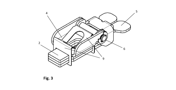
Fig. 3 and 4 shows perspective views of an embodiment of the lowering
mechanism on
top of the holding plates.
Fig. 5 shows a sectional side view of an embodiment of the lowering mechanism
with
an M-shaped spring.
Fig. 6 shows a sectional side view of an embodiment of the lowering mechanism
with
a spring shaped like a half M.
Fig. 7a, b and c shows activation of the lowering mechanism.
Fig. 8 shows a lowering plate with a M-shaped spring.
Fig. 9a and b shows three holding plates in perspective view and from the side

respectively.
Detailed description of preferred embodiments
We will describe the invention with directions up ¨ down as seen in figure 1
and rear
as pointing towards the user. The rear is the side of the operating handle 7,
as seen in
figure 1, and the front is the opposite side, or, in other words, the
direction in which
the feet are pointing.
The invention describes a lowering mechanism 12 for a hand held jacking tool
20
comprising a jacking frame 11 a jacking shaft 3 and a caulking gun jacking
mechanism. The jacking mechanism normally comprises a jacking plate 1 biased
towards an open state and a holding plate 2 above the jacking plate 1 being
biased
towards a locked state as can be seen in figure 1 and 2. The plates are
moveable along
a jacking shaft 3 and are able to grip the jacking shaft 3. It may be an
advantage to

CA 03136729 2021-10-12
WO 2020/209731 PCT/N02020/050100
3
have more than one plate, for example two or three parallel plates as seen in
figures 9 a
and b. This will reduce the wear on jacking shaft and plates and prolong the
life of the
mechanism, it will also provide a better grip as contact will be made on
several contact
regions. To obtain this effect the holes must have same size.
The plates 1, 2, moving along the jacking shaft in a caulking gun jacking
mechanism,
comprises holes slightly bigger than the cross section of the jacking shaft.
When the
plates are at a right angle with the jacking shaft the plates are moving
freely along the
shaft. When the plates have a different angle with the jacking shaft the
plates will grip
and lock to the jacking shaft. This is the main principle in a caulking gun
jacking
mechanism. In this text we call the two states the open state (right angle)
and the
gripping state (not a right angle). When we describe the different plates 1,
2, 4 in this
text we will automatically assume that a suitable hole, as shown in fig. 9a,
to fit the
jacking shaft is provided.
The lowering mechanism according to the invention comprises a lowering plate 4
on
top of the holding plate 2 being in the same gripping state as the holding
plate when
not activated. This corresponds to the lowering plate being parallel with the
holding
plate. The lowering mechanism will then be in the position as seen in figure
7a.
The lowering plate is activated by a pushing lever 5 connected with a hinge
attachment
6 to the lowering plate at a rear end towards an operating handle 7, wherein
the
pushing lever is pivoting around a pivot structure 8 connected to the lever or
holding
plate a distance backward from the hinge attachment, causing the lowering
plate 4 to
grip the jacking shaft 3 when the lever is pushed downwards. When the lowering
plate
grips the jacking shaft a further push on the lever 5, by the operator, will
push the
holding plate downwards and loosen it from the jacking shaft as seen in figure
7b. This
will allow the frame to move downward along the jacking shaft a distance until
the
holding plate reaches an angle that stops it against the jacking shaft 3 while
the
lowering plate still grips the shaft. This leaves the lowering plate and the
holding plate
with a distance between them. If the holes for the jacking shaft in the
lowering plate
and the holding plate have the same size the two plates will also be mainly
parallel as
seen in fig. 7c. The frame has moved down along the jacking shaft a distance
determined by the pivoting action of the lever while the lowering plate 4 is
stopping
the frame from further downward movement. The distance the frame is moving is
fairly similar to the distance between the parallel lowering plate and holding
plate seen
in fig 7c. This correspond to the vertical component of the angular movement
of the
arm between the hinge attachment 6 and the pivot structure 8 from the position
where
the pushing lever 5 causes the lowering plate to grip the jacking shaft. When
the
pushing lever 5 is released the spring 9 forces the lowering plate down
towards the
holding plate and the lowering mechanism is back to the position seen in fig.
7a.

CA 03136729 2021-10-12
WO 2020/209731
PCT/N02020/050100
4
The pivoting action of the lever 5 is determined by a first pivot point, Pl,
at the front
end of the lowering plate, as seen in fig 5, the hinge attachment 6, H1, and a
second
pivot point, P2, associated with the pivot structure 8 and finally the force
applied to the
lever and the length of the lever arm. This is shown in figure 5. The
positional
distribution of Pi, P2, H1 and Fl are hard to calculate and have to be tested
and tried.
If the distance Hl-P2 is to big related to the distance Pi-Hi and P2-F1 the
mechanism
will simply release the frame as with the old version. If the distance Hl-P2
is too small
related to the distance P1-H1 and P2-F1 the mechanism 12 will not be
activated.
However, the length of arms and position of pivot points must be such that an
activation force used on the pushing lever 5 to cause the lowering plate 4 to
grip the
jacking shaft 3 must be less than the force needed to release the holding
plate 2. The
activation force must also counter the force of the spring 9 holding the
lowering plate
down. Therefor the length of the pushing lever rearward of the pivoting point
8 must
be longer than the distance between the pivot point 8 and the hinge attachment
6,
preferably more than twice the distance.
The lowering plate is held in place by a spring 9 biasing at least the front
side of the
lowering plate towards the holding plate. Two embodiments of the spring are
shown in
figure 5 and 6. One is a M-shaped spring plate and the other is a spring
plate, which is
shaped as a half M. Advantageously the spring is held in place by a holding
structure
13, as shown in fig. 8, through which the holding plate (s) will fit as shown
in figure 3
and 4 and in particular fig. 8, thus holding the spring to the holding
plate(s). In one
embodiment the spring is an M-shaped spring plate 9 with a hole for the
jacking shaft
and holes for the holding plate(s) in the respective legs of the M- shape on
each side of
the jacking shaft.
The lowering mechanism is not very sensitive to the strength and positioning
of the
spring 9, whose main purpose is to push the lowering plate back down towards
the
holding plate. However, we found that it was best to avoid positioning a
center of
force too close to the hinge attachment 6. Preferably the center of force is
positioned in
front of the center of the lowering plate as seen in the figures.
The lowering mechanism is sensitive to the gap between the front and rear
sides of the
jacking shaft and the holes in the holding and lowering plates 2, 4. This
distance
should be less than a millimeter. Preferably between 0,02 and 0,3 mm. Larger
shafts
allow for larger gap. If the gap is too big the grip of the holding plate will
weaken and
if it is too small, it will tend to jam.

CA 03136729 2021-10-12
WO 2020/209731
PCT/N02020/050100
In one embodiment the rear end of the pushing lever and a release lever 10,
which is
an extension of the holding plate 2, is positioned beside each other for easy
operation
by the thumb of an operator as seen in figure 3, 4.
5 In one embodiment the pivot structure 8 is moveable in the rear ¨ front
direction
and/or in the up-down direction to regulate the distance of the downward
movement
and/or compensate for wear and tear of the jacking shaft and/or holding plate.

CA 03136729 2021-10-12
WO 2020/209731
PCT/N02020/050100
6
Inventory
1 Jacking plate
2 Holding plate
3 Jacking shaft
4 Lowering plate
5 Pushing lever
6 Hinge attachment
7 Operating handle
8 Pivot structure
9 Spring
10-Release-lever
11 Jacking frame
12 Lowering mechanism
13 Holding structure
20 Hand held jacking tool

Dessin représentatif
Une figure unique qui représente un dessin illustrant l'invention.
États administratifs

Pour une meilleure compréhension de l'état de la demande ou brevet qui figure sur cette page, la rubrique Mise en garde , et les descriptions de Brevet , États administratifs , Taxes périodiques et Historique des paiements devraient être consultées.

États administratifs

Titre Date
Date de délivrance prévu Non disponible
(86) Date de dépôt PCT 2020-04-08
(87) Date de publication PCT 2020-10-15
(85) Entrée nationale 2021-10-12
Requête d'examen 2023-11-13

Historique d'abandonnement

Il n'y a pas d'historique d'abandonnement

Taxes périodiques

Dernier paiement au montant de 125,00 $ a été reçu le 2024-02-09


 Montants des taxes pour le maintien en état à venir

Description Date Montant
Prochain paiement si taxe générale 2025-04-08 277,00 $
Prochain paiement si taxe applicable aux petites entités 2025-04-08 100,00 $

Avis : Si le paiement en totalité n'a pas été reçu au plus tard à la date indiquée, une taxe supplémentaire peut être imposée, soit une des taxes suivantes :

  • taxe de rétablissement ;
  • taxe pour paiement en souffrance ; ou
  • taxe additionnelle pour le renversement d'une péremption réputée.

Les taxes sur les brevets sont ajustées au 1er janvier de chaque année. Les montants ci-dessus sont les montants actuels s'ils sont reçus au plus tard le 31 décembre de l'année en cours.
Veuillez vous référer à la page web des taxes sur les brevets de l'OPIC pour voir tous les montants actuels des taxes.

Historique des paiements

Type de taxes Anniversaire Échéance Montant payé Date payée
Le dépôt d'une demande de brevet 2021-10-12 408,00 $ 2021-10-12
Taxe de maintien en état - Demande - nouvelle loi 2 2022-04-08 100,00 $ 2021-10-12
Taxe de maintien en état - Demande - nouvelle loi 3 2023-04-11 100,00 $ 2023-02-08
Requête d'examen 2024-04-08 816,00 $ 2023-11-13
Taxe de maintien en état - Demande - nouvelle loi 4 2024-04-08 125,00 $ 2024-02-09
Titulaires au dossier

Les titulaires actuels et antérieures au dossier sont affichés en ordre alphabétique.

Titulaires actuels au dossier
VIKING ARM AS
Titulaires antérieures au dossier
S.O.
Les propriétaires antérieurs qui ne figurent pas dans la liste des « Propriétaires au dossier » apparaîtront dans d'autres documents au dossier.
Documents

Pour visionner les fichiers sélectionnés, entrer le code reCAPTCHA :


Pour visualiser une image, cliquer sur un lien dans la colonne description du document. Pour télécharger l'image (les images), cliquer l'une ou plusieurs cases à cocher dans la première colonne et ensuite cliquer sur le bouton "Télécharger sélection en format PDF (archive Zip)" ou le bouton "Télécharger sélection (en un fichier PDF fusionné)".

Liste des documents de brevet publiés et non publiés sur la BDBC .

Si vous avez des difficultés à accéder au contenu, veuillez communiquer avec le Centre de services à la clientèle au 1-866-997-1936, ou envoyer un courriel au Centre de service à la clientèle de l'OPIC.


Description du
Document 
Date
(yyyy-mm-dd) 
Nombre de pages   Taille de l'image (Ko) 
Abrégé 2021-10-12 1 61
Revendications 2021-10-12 2 60
Dessins 2021-10-12 4 58
Description 2021-10-12 6 261
Dessins représentatifs 2021-10-12 1 8
Rapport prélim. intl. sur la brevetabilité reçu 2021-10-12 5 312
Rapport de recherche internationale 2021-10-12 2 83
Demande d'entrée en phase nationale 2021-10-12 6 165
Page couverture 2021-12-23 1 43
Modification 2024-03-27 8 292
Revendications 2024-03-27 2 84
Requête d'examen 2023-11-13 4 135