Note : Les descriptions sont présentées dans la langue officielle dans laquelle elles ont été soumises.
CA 03139065 2021-11-03
WO 2020/227114 PCT/US2020/031075
SYSTEMS AND METHODS FOR PROVIDING MONITORING, OPTIMIZATION,
AND CONTROL OF POOL/SPA EQUIPMENT USING VIDEO ANALYTICS
CROSS-REFERENCE TO RELATED APPLICATIONS
[0001] This application claims the benefit of priority to United States
Provisional Patent
Application Serial No. 62/842,939, filed on May 3, 2019, the entire disclosure
of which is
hereby incorporated by reference.
FIELD OF THE INVENTION
[0002] The present disclosure relates to systems and methods for providing
monitoring,
optimization, and control of pool/spa equipment using video analytics.
RELATED ART
[0003] Pool/spa automation systems can rely on the use of external sensors
located in close
proximity to the operation that is intended to be monitored. Each operation
may require the use
of multiple sensors with specialized functions in order to provide the system
with the required
telemetry data to perform automated behavior. Additionally, with the growth of
computer vision
technologies, machine learning, and artificial intelligence, it would be
beneficial if such
technologies could augment the present capabilities of pool/spa automation
systems.
[0004] Accordingly, what is needed is an effective system that can actively
monitor multiple
operations concurrently using an image capture device and computer vision
technologies, thus
reducing the complexity and cost of the infrastructure required by current
pool/spa automation
systems.
1
CA 03139065 2021-11-03
WO 2020/227114 PCT/US2020/031075
SUMMARY OF THE INVENTION
[0005] The present disclosure relates to systems and methods for providing
monitoring,
optimization, and control of pool/spa equipment using video analytics. The
present disclosure
can include a camera system in communication with a microprocessor the
monitors a pool/spa
environment, identifies objects of interest in the pool/spa environment,
classifies the objects of
interest, and identifies scenarios and/or learned behaviors of objects
utilizing video analytics
software. These analytics can include object detection in combination with
tracking algorithms
in order to precisely locate objects of interest within the video frames.
Further image
classification and scene labeling algorithms may be used to classify the
object in order to define
its attributes. Once processed, the system can transmit alerts or commands to
pool/spa users and
devices to modify the operation thereof based on the identified attributes of
the objects of
interest.
2
CA 03139065 2021-11-03
WO 2020/227114 PCT/US2020/031075
BRIEF DESCRIPTION OF THE DRAWINGS
[0006] The foregoing features of the disclosure will be apparent from the
following Detailed
Description, taken in connection with the accompanying drawings, in which:
[0007] FIG. 1 is a diagram illustrating the system of the present
disclosure;
[0008] FIG. 2 is a diagram illustrating an image frame captured by the
system of FIG. 1;
[0009] FIG. 3 is a flowchart illustrating processing steps carried out by
the system of FIG. 1;
and
[0010] FIG. 4 is a block diagram illustrating hardware and software
components of a system
of the present disclosure.
3
CA 03139065 2021-11-03
WO 2020/227114 PCT/US2020/031075
DETAILED DESCRIPTION
[0011] The present disclosure relates to systems and methods for providing
network
connectivity and remote monitoring, optimization and control of pool/spa
equipment, as
discussed in detail below in connection with FIGS. 1-4.
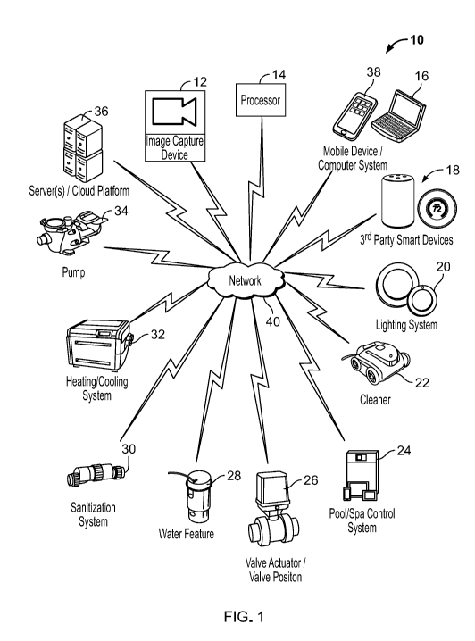
[0012] FIG. 1 is a diagram illustrating the system 10 of the present
disclosure. Generally,
the system 10 monitors a pool/spa environment using an image capture device 12
directed
towards the pool/spa environment, identifies one or more objects of interest
and attributes
thereof using a processor 14 that applies video analytics algorithms to image
and/or video
information obtained by the image capture device 12, and determines an action
to be taken based
on this information. For example, the system 10 can communicate an alert to a
user, or control
the operation of one or more pool/spa devices based on the attributes of the
one or more objects
of interest.
[0013] The image capture device 12 can include one or more of a high
resolution camera, an
infrared (IR) or thermal imaging camera, or a light detection and ranging
(LIDAR) system. The
processor 14 can be integrated into the image capture device 12, or it can be
a separate device.
For example, the processor 14 can be located at the pool/spa environment and
communicate with
the image capture device 12 by way of a local network, or the processor 14
could be located
remotely, such as in a cloud-based pool/spa control system and communicate
with the image
capture device 12 by way of the Internet.
[0014] As shown in FIG. 1, the system 10 can include various types of
pool/spa equipment,
such as, a pump 34, a heating/cooling system 32, a sanitization system 30, a
water feature 28, a
valve actuator 26, a pool/spa control system 24, a pool cleaner 22, and/or a
lighting system 20.
The system 10 can also include, or be in communication with, other systems
such as a remote
server/"cloud"-based control system 36, a computer system 16, a mobile device
38 (e.g., smart
4
CA 03139065 2021-11-03
WO 2020/227114 PCT/US2020/031075
phone), 3rd party smart devices 18 (e,g., voice-enabled speakers, connected
home appliances,
etc.), and combinations thereof.
[0015] The devices of system 10 can communicate with each other over a
network 40, which
could include, but is not limited to, the Internet. Of course, as would be
known to one of
ordinary skill in the art, the network 40 can provide for communication
between the devices of
system 10 using one or more of wired (e.g., RS485, ethernet, USB, serial,
etc.), wireless (e.g.,
Wifi, Bluetooth, ZigBee, ZWave, cellular, thread, etc.), and direct
communication protocols and
combinations thereof. While the foregoing discussion references network 40, it
shall be
understood that the present system can be a self-contained system that does
not include network
connectivity or cloud communication capabilities. For example, in such a
system, the image
capture device 12 and processor 14 could be directly connected to one or more
pool or spa
devices by way of a serial connection or any other suitable direct
communication protocols.
[0016] FIG. 2 is an example of an image frame, indicated generally at 50,
captured by the
image capture device 12 of the system 10. As shown in FIG. 2, a first object
of interest 52a
(e.g., a person) and a second object of interest 52b (e.g., a pool), contained
within the field of
view 54 of the image capture device 12, are identified within bounding boxes
56a and 56b.
Within bounding boxes 56a and 56b, features of interest 58a and 58b can be
identified by the
system 10 and analyzed to further classify regions of the object of interest
52a and 52b. For
example, as shown in FIG. 2, the first object of interest 52a includes
features of interest 58a
(e.g., limbs of the person) and regions 60a (the person and the area
surrounding the person).
Similarly, the second object of interest 52b includes feature of interest 58b
(e.g., water) and
regions 60b (the pool and the deck surrounding the pool). It should be
understood that the
image frame illustrated in FIG. 2, and discussed above, is an exemplary image
frame, and in
operation the image capture device 12 can capture image frames that include
one of more of the
CA 03139065 2021-11-03
WO 2020/227114 PCT/US2020/031075
pool/spa components associated with the pool, as discussed in connection with
FIG. 1 (e.g.,
water features, pumps, lights, heaters, sanitization systems, cleaners,
valves, etc.).
[0017] FIG. 3 is a flowchart illustrating processing steps carried out by
the system 10 of the
present disclosure. In step 70, the image capture device 12 captures one or
more image frames
of the pool/spa environment contained within the device's field of view. The
process then
proceeds to step 72, where the system 10 processes the one or more image
frames to identify
objects of interest contained therein. Specifically, the image frames are
analyzed by the
processor 14 using a suitable computer vision (video analysis) algorithm to
detect objects of
interest within the video frames. For example, such an algorithm can utilize a
multi-scale
strategy for refining the detection within a bounding box (see, e.g., FIG. 2)
used to identify an
object of interest. The process then proceeds to step 74, where the system 10
identifies features
of interest of the object of interest. For example, convolutional neural
networks (CNNs) can be
used to identify the features of interest within the bounding box and can
further classify regions
of the object. Furthermore, the video analysis algorithm can include a pool of
multiple
convolutional neural networks that can be stacked or layered. The process then
proceeds to step
76, where the system 10 classifies the object of interest. For example, the
system 10 can
identify a particular object of interest as a person and another object of
interest as a pool or spa
(see, e.g., FIG. 2). Additionally, algorithms for scene labeling can be
further utilized for
definition of objects or areas contained within the image/video. It is also
contemplated by the
present disclosure that steps 74 and 76 can be repeated one or more times in
order to identify
additional features of interest and further refine the object of interest
classification. Steps 74 and
76 can also be repeated to identify additional features of interest if
classification of the object of
interest is initially unsuccessful. The process then proceeds to step 78,
where the system 10
determines attributes of the objects of interest. For example, once
classified, the system 10 can
track and/or measure one or more objects of interest and monitor their
relationship to one
6
CA 03139065 2021-11-03
WO 2020/227114 PCT/US2020/031075
another (e.g., determining that an unattended toddler is approaching the pool
by classifying one
object of interest as a toddler, classifying another object of interest as a
pool, and tracking how
close the toddler is getting to the pool). The system 10 can provide advanced
telemetry
regarding how an object of interest interacts with the pool/spa environment
and the video
analysis algorithms analyze this data in order to form "learned" behaviors
that enable the system
to predict a required automated behavior. For example, the system 10 can
retrieve pre-learned
features for comparison to current object features to determine changes in
appearance of the
object frame by frame (e.g., determining that a person starts dancing by
comparing pre-learned
dancing features to current features of an object of interest classified as a
person). The process
then proceeds to step 80, where the system 10 determines an action to be taken
based on the
attributes of the objects of interest. For example, if the system 10
determines that an unattended
toddler is getting too close to the pool, the system can determine that a
preventative action
should be taken, such as, sounding an alarm or transmitting an alert to a
user's mobile device via
SMS or the like. The process then proceeds to step 82, where the system
initiates the action
determined in step 82 and then finally returns to step 70, where the system
captures additional
image frames and continues to monitor the pool/spa environment.
[0018] According to the process described in connection with FIG. 3, by
monitoring the
pool/spa environment using the image capture device 12 and processing the
information
therefrom using video analytics algorithm(s) running on the processor 14, the
system 10 can
provide commands and feedback based on complex real-time events, thereby
enabling automatic
notifications and adjustment of pool/spa devices without the use of a
plurality of dedicated
sensors and other monitoring devices traditionally required to collect data
regarding user or pool
equipment behavior. For example, pool/spa water features are commonly
controlled via
manipulation of pump speed and a pool/spa automation system may not have the
sensing
devices necessary to detect if the water feature is flooding the pool/spa deck
or draining the pool
7
CA 03139065 2021-11-03
WO 2020/227114 PCT/US2020/031075
due to an external force (e.g., obstruction or high winds). However, according
to the process
described in connection with FIG. 3, the system 10 can quickly identify if a
water feature 28 is
no longer entering a body of water (e.g., by identifying the pool and water
feature, classifying
them as such, identifying their features and regions, and monitoring their
relationship to one
another). The system 10 can then automatically transmit an instruction to the
pool/spa pump 34
or control system 24 to reduce the pump speed, thereby optimizing the
operation of the water
feature 28 without requiring intervention of the user. Additionally, the
system 10 can provide the
ability for the user to specify operation of the water feature 28 based on
alternative parameters
such as desired height of a water stream.
[0019] According to some aspects of the present disclosure, using the
process described in
connection with FIG. 3, the system 10 can also: perform object recognition of
adults and/or pets
to determine bather load and optimize sanitization system 30 and pump 34
operation; perform
object, or facial, recognition of specific users to automatically operate
specific light shows or
implement other preferences; monitor usage of pool to analyze potential
chemical demand and
adjust the sanitization system 30; determine size or gender of user and
prioritize settings; set
custom safety zones for alerts based on bather detection (e.g., deep end vs.
shallow end of pool)
and distance from pool (e.g., 10 ft. zone around pool/spa for toddlers);
monitor an individual
bather, count the bather's number of laps, and adjust the lighting system
colors based on number
of laps or speed; identify swimmers vs. non swimmers; modify scenarios based
on time of day
or weather; shutoff water features based on weather (e.g., wind) or turn on
pool cleaner; enable
zone-based activation of pool/spa features (e.g., entering spa turns on spa or
exiting shuts off
spa); initiate pool/spa equipment sleep mode based on no activity being
detected; detect the
presence of a pool cover and use this information as a variable for alarm
systems; perform water
quality check (e.g., by visually monitoring water clarity, color, turbidity);
perform diagnostics of
pool/spa systems (e.g., identify that a light is out); recognize hand gestures
and initiate
8
CA 03139065 2021-11-03
WO 2020/227114 PCT/US2020/031075
commands based thereon; detect leaks on equipment pad; monitor water level;
change height
setting of water features remotely; recognize water feature stream (e.g.,
height, distance, and
flow) and adjust pump or valve to optimize flow; recognize high debris in pool
to activate
cleaner, activate or change skimmers, or activate in-floor cleaning system;
step-up chemical
automation if rain is detected; monitor solar load on pool and automatically
adjust pool/spa
chemistry; detect unintentional fires and monitor fire safe zones (e.g., child
dependent);
determine whether a life guard is on duty or not and transmit an alert, alarm,
or indicator; detect
if a user is impaired (e.g., stumbling, swaying arms, or falling); determine
that a user is dancing
and automatically turn on music; notify a user if a specific person enters a
designated area;
communicate with lighting system or other backyard systems to perform enhanced
motion and
sound detection; identify specific animals entering or exiting the pool/spa
environment (e.g.,
bear or alligator alarm); transmit an alert if pets are in proximity to
designated pool/spa area;
perform self-diagnostics (e.g., detect a dirty lens, connectivity issues,
etc.); monitor bather load
and automatically adjust filter turn-over rate; recognize when the pool is not
in use and initiate
an "Away Mode" to improve energy efficiency; notify a Servicer based on
detected pool/spa
device conditions; monitor and/or transmit an alert to a user based on time
spent by particular
person in a hot tub (e.g., child vs. adult); a person is detected diving into
a pool/spa; transmit a
notification or alert to a user when running near an activity zone (e.g.,
unsafe behavior) is
detected; detect furniture in pool (e.g., blown in by storm) and transmit a
notification or alert to
a user; identify safety floatation items (e.g., swimmies or water wings);
communicate with smart
home devices (e.g., Alexa, google home, etc.) and home security systems;
identify a pool
servicer and track his/her time at the pool/spa site; determine pool/spa deck
conditions (e.g., icy,
slippery, etc.) and take appropriate action; determine temperature of pool/spa
or deck using IR
camera and provide warnings or control of pool/spa equipment; deploy
awnings/shades based on
determined sunshine/temperature; determine the amount of water on pool/spa
cover and
9
CA 03139065 2021-11-03
WO 2020/227114 PCT/US2020/031075
determine if winterization/cover mode is appropriate; recognize unsafe bathing
conditions for
classes of users (e.g., cleaner in pool with children, pool partially covered
with children present);
recognize where in the pool/spa the pool monitor resides; and determine that a
bather is close to
the pool/spa drain and activate an alarm.
[0020] As discussed above, the image capture device 12 of the present
disclosure can
include a light detection and ranging (LIDAR) system. According to some
aspects of the
present disclosure, the LIDAR system illuminates the pool/spa environment, or
a particular
object of interest, with pulsed laser light and measures the return times of
reflected pulses to
provide a digital three dimensional (3D) representation of the pool/spa
environment or object of
interest. The system 10 can then use these 3D representations of to identify
objects of interest,
determine attributes of the objects of interest, and take appropriate action,
as discussed in
connection with FIG. 3.
[0021] FIG. 4 is a diagram showing hardware and software components of a
computer
system 102 on which the system 10 of the present disclosure can be
implemented. The
computer system 102 can include a storage device 104, a video analysis
software module 106
(computer code which carries out the processing steps described herein), a
network interface
108, a communications bus 110, a central processing unit (CPU)
(microprocessor) 112, a
random access memory (RAM) 114, and one or more input devices 116, such as a
keyboard,
mouse, etc. The computer system 102 can also include a display (e.g., liquid
crystal display
(LCD), cathode ray tube (CRT), etc.). The storage device 104 can comprise any
suitable,
computer-readable storage medium such as disk, non-volatile memory (e.g., read-
only memory
(ROM), eraseable programmable ROM (EPROM), electrically-eraseable programmable
ROM
(EEPROM), flash memory, field-programmable gate array (FPGA), etc.). The
computer system
102 can be a networked computer system, a personal computer, a server, a smart
phone, tablet
CA 03139065 2021-11-03
WO 2020/227114 PCT/US2020/031075
computer etc. It is noted that the server 102 need not be a networked server,
and indeed, could
be a stand-alone computer system.
[0022] The functionality provided by the present disclosure can be provided
by video
analysis algorithms 106, which can be embodied as computer-readable program
code stored on
the storage device 104 and executed by the CPU 112 using any suitable, high or
low level
computing language, such as Python, Java, C, C++, C#, .NET, MATLAB, etc. The
network
interface 108 can include an Ethernet network interface device, a wireless
network interface
device, or any other suitable device which permits the system 102 to
communicate via a
network. The CPU 112 can include any suitable single-core or multiple-core
microprocessor of
any suitable architecture that is capable of implementing and running the
video analysis
algorithms 106 (e.g., Intel processor). The random access memory 114 can
include any suitable,
high-speed, random access memory typical of most modern computers, such as
dynamic RAM
(DRAM), etc.
[0023] Having thus described the system and method in detail, it is to be
understood that the
foregoing description is not intended to limit the spirit or scope thereof. It
will be understood
that the embodiments of the present disclosure described herein are merely
exemplary and that a
person skilled in the art can make any variations and modification without
departing from the
spirit and scope of the disclosure. All such variations and modifications,
including those
discussed above, are intended to be included within the scope of the
disclosure.
11