Sélection de la langue

Search

Sommaire du brevet 3139664 

Énoncé de désistement de responsabilité concernant l'information provenant de tiers

Une partie des informations de ce site Web a été fournie par des sources externes. Le gouvernement du Canada n'assume aucune responsabilité concernant la précision, l'actualité ou la fiabilité des informations fournies par les sources externes. Les utilisateurs qui désirent employer cette information devraient consulter directement la source des informations. Le contenu fourni par les sources externes n'est pas assujetti aux exigences sur les langues officielles, la protection des renseignements personnels et l'accessibilité.

Disponibilité de l'Abrégé et des Revendications

L'apparition de différences dans le texte et l'image des Revendications et de l'Abrégé dépend du moment auquel le document est publié. Les textes des Revendications et de l'Abrégé sont affichés :

  • lorsque la demande peut être examinée par le public;
  • lorsque le brevet est émis (délivrance).
(12) Demande de brevet: (11) CA 3139664
(54) Titre français: APPAREIL DE GALVANISATION EN CONTINU POUR DE MULTIPLES TIGES
(54) Titre anglais: CONTINUOUS GALVANIZING APPARATUS FOR MULTIPLE RODS
Statut: Examen demandé
Données bibliographiques
(51) Classification internationale des brevets (CIB):
  • C23C 2/00 (2006.01)
  • C23C 2/06 (2006.01)
  • C23C 2/38 (2006.01)
(72) Inventeurs :
  • MASON, CHRISTOPHER STEPHEN (Etats-Unis d'Amérique)
  • PATTERSON, RUSSELL WAYNE (Etats-Unis d'Amérique)
(73) Titulaires :
  • WESTERN TECHNOLOGIES, INC. (Etats-Unis d'Amérique)
(71) Demandeurs :
  • WESTERN TECHNOLOGIES, INC. (Etats-Unis d'Amérique)
(74) Agent: SMART & BIGGAR LP
(74) Co-agent:
(45) Délivré:
(86) Date de dépôt PCT: 2019-08-29
(87) Mise à la disponibilité du public: 2020-11-19
Requête d'examen: 2022-02-07
Licence disponible: S.O.
(25) Langue des documents déposés: Anglais

Traité de coopération en matière de brevets (PCT): Oui
(86) Numéro de la demande PCT: PCT/US2019/048694
(87) Numéro de publication internationale PCT: WO2020/231454
(85) Entrée nationale: 2021-11-08

(30) Données de priorité de la demande:
Numéro de la demande Pays / territoire Date
16/411,412 Etats-Unis d'Amérique 2019-05-14

Abrégés

Abrégé français

L'invention concerne un appareil de galvanisation en continu pour de multiples tiges. L'appareil comprend un chaudron pour chauffer et retenir un liquide dans celui-ci, au moins une partie du chaudron ayant une partie supérieure ouverte. Un ensemble cuvette retient le liquide. L'ensemble cuvette est disposé au-dessus de la partie supérieure ouverte du chaudron au-dessus du niveau de liquide, l'ensemble cuvette ayant au moins une chambre inférieure à l'intérieur du chaudron au-dessous d'un niveau de liquide dans le chaudron. Une pompe dans la chambre inférieure aspire le liquide depuis le chaudron vers l'ensemble cuvette. Une pluralité d'ouvertures d'entrée sont disposées dans l'ensemble cuvette conjointement avec une pluralité d'ouvertures de sortie opposées aux ouvertures d'entrée et alignées avec celles-ci. Des tubes adjacents dans l'ensemble cuvette sont alignés avec la pluralité d'ouvertures d'entrée et de sortie.


Abrégé anglais

A continuous galvanizing apparatus for multiple rods. The apparatus includes a kettle for heating and retaining a liquid therein with at least a portion of the kettle having an open top. A trough assembly retains liquid therein. The trough assembly is arranged above the kettle open top above the liquid level, with the trough assembly having at least one lower chamber within the kettle below a level of the liquid in the kettle. A pump in the lower chamber draws liquid from the kettle to the trough assembly. A plurality of entry openings are provided in the trough assembly along with a plurality of exit openings opposed to and aligned with the entry openings. Adjacent tubes in the trough assembly are aligned with the plurality of entry and exit openings.

Revendications

Note : Les revendications sont présentées dans la langue officielle dans laquelle elles ont été soumises.


7
WHAT IS CLAIIVIED IS:
1. A continuous galvanizing apparatus for multiple rods, which apparatus
comprises :
a kettle for heating and retaining a liquid therein, at least a portion of
said kettle
having an open top;
a trough assembly for retaining said liquid therein, said trough assembly
having
a trough arranged above said kettle open top, said trough assembly having at
least one lower
chamber within said kettle below a level of said liquid in said kettle;
a pump in said lower chamber to draw said liquid from said kettle to said
trough
assembly; and
a plurality of entry openings in said trough assembly and a plurality of exit
openings in said trough opposed to and aligned with said entry openings.
2. The continuous galvanizing apparatus for multiple rods as set forth in
Claim 1
including a plurality of adjacent tubes in said trough assembly aligned with
said plurality of
entry openings and said plurality of exit openings.
3. The continuous galvanizing apparatus for multiple rods as set forth in
Claim 2
wherein each of said plurality of adjacent tubes includes a plurality of slots
to permit passage
of said liquid.
4. The continuous galvanizing apparatus for multiple rods as set forth in
Claim 1
wherein each said entry opening includes a tapered entry guide.

8
5. The continuous galvanizing apparatus for multiple rods as set forth in
Claim 1
wherein each said exit opening includes a tapered exit guide.
6. The continuous galvanizing apparatus for multiple rods as set forth in
Claim 4
including an angled deflector beneath said tapered entry guides.
7. The continuous galvanizing apparatus for multiple rods as set forth in
Claim 5
including an angled deflector beneath said tapered exit guides.
8. The continuous galvanizing apparatus for multiple rods as set forth in
Claim 1
wherein said rods are metal rebar rods.
9. The continuous galvanizing apparatus for multiple rods as set forth in
Claim 2
wherein each of said plurality of adjacent tubes is cylindrical and parallel
to each other.
10. The continuous galvanizing apparatus for multiple rods as set forth in
Claim 1
including an overflow chamber separated from said trough by a weir and wherein
said overflow
chamber is in fluid communication with said kettle.
11. The continuous galvanizing apparatus for multiple rods as set forth in
Claim 1
wherein said liquid is liquid zinc or liquid zinc alloy.
12. A continuous galvanizing apparatus for multiple rods, which apparatus
comprises :

9
a kettle for heating and retaining a liquid therein, at least a portion of
said kettle
having an open top;
a trough assembly for retaining said liquid therein, said trough assembly
having
a trough arranged above said kettle open top;
a pump to draw liquid from said kettle to said trough assembly;
a plurality of entry openings in said trough and a plurality of exit openings
in
said trough opposed to and aligned with said entry openings; and
a plurality of adjacent tubes in said trough aligned with said plurality of
entry
openings and said plurality of exit openings.
13. The continuous galvanizing apparatus for multiple rods as set forth in
Claim 12
wherein each of said plurality of adjacent tubes includes a plurality of slots
to permit passage
of said liquid.
14. The continuous galvanizing apparatus for multiple rods as set forth in
Claim 12
wherein each said entry opening includes a tapered entry guide.
15. The continuous galvanizing apparatus for multiple rods as set forth in
Claim 12
wherein each said exit opening includes a tapered exit guide.
16. The continuous galvanizing apparatus for multiple rods as set forth in
Claim 14
including an angled deflector beneath said tapered entry guide.
17. The continuous galvanizing apparatus for multiple rods as set forth in
Claim 15

10
including an angled deflector beneath said tapered exit guide.
18. The continuous galvanizing apparatus for multiple rods as set forth in
Claim 12
wherein said rods are metal rebar rods.
19. The continuous galvanizing apparatus for multiple rods as set forth in
Claim 12
wherein each of said plurality of adjacent tubes is cylindrical and parallel
to each other.
20. The continuous galvanizing apparatus for multiple rods as set forth in
Claim 12
including an overflow chamber separated from said trough by a weir and wherein
said overflow
chamber is in fluid communication with said kettle.

Description

Note : Les descriptions sont présentées dans la langue officielle dans laquelle elles ont été soumises.

CA 03139664 2021-11-08
WO 2020/231454
PCT/US2019/048694
1
CONTINUOUS GALVANIZING APPARATUS FOR MULTIPLE RODS
BACKGROUND OF THE INVENTION
1. Cross-Reference to Related Applications.
This application is based on and claims priority to U.S. Patent Application
Serial No.
16/411,412, filed May 14, 2019, which is a continuation-in-part of U.S. Patent
Application
Serial No. 15/955,389, filed April 17, 2018, which claims priority to and the
benefit of U.S.
Provisional Patent Application Serial No. 62/486,593, filed April 18, 2017,
each of which is
incorporated herein by reference in its entirety.
2. Field of the Invention.
The present invention relates to an apparatus to simultaneously galvanize
multiple rods
and a process therefor. In particular, the present invention is directed to a
continuous
galvanizing apparatus and a process therefor that can simultaneously galvanize
multiple rebar
rods continuously without any manual intervention.
3. Description of the Related Art.
The process of galvanizing steel or iron has been known for over a century. A
layer
of zinc or alloyed zinc forms to the surface of the steel or iron.
Galvanization provides both barrier protection and corrosion resistance.
Hot-dip galvanization is known wherein a metal object is dipped into a liquid
bath of
the zinc. Upon cooling, the zinc forms a protective barrier coating and
provides corrosion
resistance. More recently, iron or steel materials have been hot-dipped in a
continuous line.
In addition, continuous galvanization of items has been performed by passing
an item through
a flooded trough.
Notwithstanding the foregoing, there remains a need for a continuous
galvanizing
apparatus and process to simultaneously galvanize a number of items without
any manual

CA 03139664 2021-11-08
WO 2020/231454
PCT/US2019/048694
2
intervention.
It is desirable to minimize turbulence of the liquid zinc or liquid alloyed
zinc as the
objects are coating in order to minimize foaming.
There also remains a need to provide a continuous galvanizing apparatus and
process
which efficiently galvanizes items while minimizing turbulence of the liquid
bath.
There also remains a need to provide a continuous galvanizing apparatus and
process
which minimizes foaming of galvanizing liquid while maximizing galvanizing
efficiency.
SUMMARY OF THE INVENTION
The present invention is directed to a continuous galvanizing apparatus for
multiple
rods. The apparatus includes a kettle for heating and retaining a liquid
therein with at least a
portion of the kettle having an open top. In one embodiment, the liquid is
liquid zinc or liquid
zinc alloy.
A trough assembly includes an elongated trough for retaining the liquid
therein with the
trough arranged above the kettle open top. The trough assembly has at least
one lower
chamber positioned and located within the kettle below a level of liquid in
the kettle.
A pump or pumps in the lower chamber of the trough assembly draws liquid from
the
kettle and moves it into the lower chamber of the trough assembly. When the
lower chamber
of the trough assembly has filled, the trough is thereafter filled. An
overflow chamber is
separated from the trough of the trough assembly by a weir wherein the
overflow chamber is
zo in fluid communication with said kettle.
A plurality of entry openings are provided in the trough of the trough
assembly. A
plurality of exit openings in the trough are opposed to and aligned with the
entry openings.
Each entry opening includes a tapered entry guide. Each exit opening includes
a tapered exit
guide.

CA 03139664 2021-11-08
WO 2020/231454
PCT/US2019/048694
3
An angled deflector is positioned beneath the tapered entry guides. Likewise,
an
angled deflector is positioned beneath the tapered exit guides.
A plurality of adjacent, parallel tubes in the elongated trough of the trough
assembly
are aligned with the plurality of entry openings and with the plurality of
exit openings. Each
of the plurality of adjacent tubes includes a plurality of slots in order to
permit passage of the
liquid.
BRIEF DESCRIPTION OF THE DRAWINGS
Figure 1 is a top view of a continuous galvanizing apparatus for multiple rods
constructed in accordance with the present invention;
Figure 2 is a sectional view taken along section line 2-2 of Figure 1;
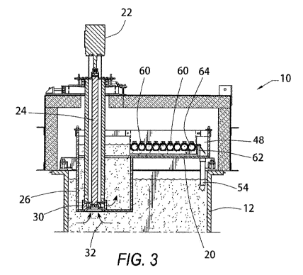
Figure 3 is a sectional view taken along section line 3-3 of Figure 1;
Figure 4 is an enlarged, partial view of a portion of the apparatus shown in
Figure 3;
and
Figure 5 is a sectional view taken along section line 5-5 of Figure 4.
DETAILED DESCRIPTION OF THE INVENTION
The embodiments discussed herein are merely illustrative of specific manners
in which
to make and use the invention and are not to be interpreted as limiting the
scope.
While the invention has been described with a certain degree of particularity,
it is to be
noted that many modifications may be made in the details of the invention's
construction and
zo the arrangement of its components without departing from the scope of
this disclosure. It is
understood that the invention is not limited to the embodiments set forth
herein for purposes of
exemplification.
Referring to the drawings in detail, Figure 1 is a top view of a continuous
galvanizing
apparatus 10 for multiple rods.

CA 03139664 2021-11-08
WO 2020/231454
PCT/US2019/048694
4
The apparatus 10 contains a liquid reservoir or kettle 12 for heating and
retaining a
liquid therein.
Figure 2 illustrates a view taken along section line 2-2 of Figure 1 while
Figure 3
illustrates a view taken along section line 3-3 of Figure 1. The apparatus 10
includes a liquid
reservoir or kettle 12 acting as a storage container for the liquid. The
kettle 12 is a
substantially elongated container which retains and heats a liquid therein. In
a preferred
embodiment, the liquid is heated liquid zinc or heated zinc and aluminum
alloy.
As seen in Figure 1, a portion 14 of the top of the kettle 12 may be closed
although at
least a portion 16 of the kettle 12 contains an open top.
A trough assembly is arranged above the open top portion 16 of the kettle 12.
The
trough assembly includes a trough 20 arranged above an open top of the kettle.
Braces or
beams support the trough 20 above the kettle.
The trough assembly includes at least one lower chamber 26 which is at least
partially
within the kettle 12 and at least partially below a level of liquid in the
kettle 12.
In the embodiment shown in Figure 2, two lower chambers 26 are utilized
although a
different number may be used within the spirit and scope of the present
embodiment.
As will be explained, the lower chamber 26 is substantially fluid tight with
an open top
in fluid communication with the trough 20. In addition, the lower chamber 26
has a series of
lower pump inlet openings which operate in conjunction with pumps 30 (to be
described).
zo
Accordingly, liquid in the trough assembly will initially fill the lower
chamber 26 and, as the
liquid level rises, thereafter fill the trough 20.
Arrow 18 in Figures 1 and 2 illustrates the direction that the rebar (not
seen) will travel
entering into and passing through the apparatus 10.
As best seen in Figures 2, 3, and 4, at least one pump 30 in each lower
chamber 26 will

CA 03139664 2021-11-08
WO 2020/231454
PCT/US2019/048694
draw liquid from the kettle 12 into the lower chamber 26, as shown by arrows
32. In the
embodiment shown, three pumps 30 are utilized. Motors 22 connected to the
pumps 30 by
shafts 24 drive the pumps 30. The motors 22 may be located above the kettle
12.
When the pumps 30 are turned off, zinc is permitted to drain from the lower
chamber
5 26 back through the lower pump inlet openings to the kettle 12.
As seen in Figures 1, 2, and 5, a plurality of entry openings 40 are provided
in the trough
20.
The entry openings 40 pass through a wall of the trough 20. In the embodiment
shown,
each entry opening 40 has a tapered entry guide 42 extending from the trough.
Accordingly,
the entry guide 42 acts as a guide for the incoming metal rods or rebar (not
shown).
The trough 20 also includes a plurality of exit openings 50. In the embodiment
shown,
a tapered exit guide 52 extends from each exit opening 50 and acts as a guide
for the metal rods
or rebar exiting the trough assembly.
In the trough 20 are a plurality or series of adjacent tubes 60. In the
embodiment
shown, the tubes 60 are cylindrical and substantially parallel to each other
although other
arrangements are possible. The tubes 60 extend in a substantially transverse
direction within
the elongated trough 20. The adjacent tubes 60 are aligned with the plurality
of entry openings
40 and aligned with the exit openings 50 so that they provide a guide for the
metal rods or rebar
passing therethrough.
Each of the tubes has a plurality of slots 64 to permit passage of liquid from
the trough
zo 20 into and out of the tubes 60.
The tapered entry guides 42 are above the open top 16 of the kettle 12.
Accordingly,
liquid from the trough 20 may pass through the entry openings 40, through the
tapered entry
guides 42, and thereafter fall by gravity into the open top of the kettle. A
series of angled
deflectors 66 reduce splashing and turbulence of the liquid as it moves toward
the kettle.

CA 03139664 2021-11-08
WO 2020/231454
PCT/US2019/048694
6
Likewise, the tapered exit guides 52 are above the open top of the kettle 12.
A series
of exit angled deflectors 70 reduce splashing and turbulence of the liquid as
it moves toward
the kettle.
A drain or drains 54 assists in permitting liquid to return to the kettle 12.
Accordingly,
the liquid moves in a continuous loop from the kettle 12 into the lower
chamber of the trough
assembly, into the trough 20, into the adjacent tubes where the rebar is
galvanized, over a weir
62, and back to the kettle 12.
Returning to a consideration of Figures 2 and 5, an angled deflector or
deflectors 56 are
positioned beneath the tapered entry guides.
Likewise, an angled deflector or deflectors 58 are positioned beneath the
tapered exit
guides.
Returning to a consideration of Figures 1, 3, and 4, an overflow chamber 48 is
separated
from the trough 20 by the weir 62.
Whereas, the invention has been described in relation to the drawings attached
hereto,
it should be understood that other and further modifications, apart from those
shown or
suggested herein, may be made within the scope of this invention.

Dessin représentatif
Une figure unique qui représente un dessin illustrant l'invention.
États administratifs

Pour une meilleure compréhension de l'état de la demande ou brevet qui figure sur cette page, la rubrique Mise en garde , et les descriptions de Brevet , États administratifs , Taxes périodiques et Historique des paiements devraient être consultées.

États administratifs

Titre Date
Date de délivrance prévu Non disponible
(86) Date de dépôt PCT 2019-08-29
(87) Date de publication PCT 2020-11-19
(85) Entrée nationale 2021-11-08
Requête d'examen 2022-02-07

Historique d'abandonnement

Il n'y a pas d'historique d'abandonnement

Taxes périodiques

Dernier paiement au montant de 100,00 $ a été reçu le 2023-08-01


 Montants des taxes pour le maintien en état à venir

Description Date Montant
Prochain paiement si taxe applicable aux petites entités 2024-08-29 100,00 $
Prochain paiement si taxe générale 2024-08-29 277,00 $

Avis : Si le paiement en totalité n'a pas été reçu au plus tard à la date indiquée, une taxe supplémentaire peut être imposée, soit une des taxes suivantes :

  • taxe de rétablissement ;
  • taxe pour paiement en souffrance ; ou
  • taxe additionnelle pour le renversement d'une péremption réputée.

Les taxes sur les brevets sont ajustées au 1er janvier de chaque année. Les montants ci-dessus sont les montants actuels s'ils sont reçus au plus tard le 31 décembre de l'année en cours.
Veuillez vous référer à la page web des taxes sur les brevets de l'OPIC pour voir tous les montants actuels des taxes.

Historique des paiements

Type de taxes Anniversaire Échéance Montant payé Date payée
Taxe de maintien en état - Demande - nouvelle loi 2 2021-08-30 100,00 $ 2021-11-08
Le dépôt d'une demande de brevet 2021-11-08 408,00 $ 2021-11-08
Requête d'examen 2024-08-29 814,37 $ 2022-02-07
Taxe de maintien en état - Demande - nouvelle loi 3 2022-08-29 100,00 $ 2022-07-22
Taxe de maintien en état - Demande - nouvelle loi 4 2023-08-29 100,00 $ 2023-08-01
Titulaires au dossier

Les titulaires actuels et antérieures au dossier sont affichés en ordre alphabétique.

Titulaires actuels au dossier
WESTERN TECHNOLOGIES, INC.
Titulaires antérieures au dossier
S.O.
Les propriétaires antérieurs qui ne figurent pas dans la liste des « Propriétaires au dossier » apparaîtront dans d'autres documents au dossier.
Documents

Pour visionner les fichiers sélectionnés, entrer le code reCAPTCHA :


Pour visualiser une image, cliquer sur un lien dans la colonne description du document. Pour télécharger l'image (les images), cliquer l'une ou plusieurs cases à cocher dans la première colonne et ensuite cliquer sur le bouton "Télécharger sélection en format PDF (archive Zip)" ou le bouton "Télécharger sélection (en un fichier PDF fusionné)".

Liste des documents de brevet publiés et non publiés sur la BDBC .

Si vous avez des difficultés à accéder au contenu, veuillez communiquer avec le Centre de services à la clientèle au 1-866-997-1936, ou envoyer un courriel au Centre de service à la clientèle de l'OPIC.


Description du
Document 
Date
(yyyy-mm-dd) 
Nombre de pages   Taille de l'image (Ko) 
Abrégé 2021-11-08 2 91
Revendications 2021-11-08 4 102
Dessins 2021-11-08 5 281
Description 2021-11-08 6 225
Dessins représentatifs 2021-11-08 1 39
Rapport de recherche internationale 2021-11-08 2 96
Demande d'entrée en phase nationale 2021-11-08 6 209
Page couverture 2022-01-11 1 63
Requête d'examen / Modification 2022-02-07 9 262
Revendications 2022-02-07 3 67
Demande d'examen 2022-12-06 4 185
Modification 2023-04-06 16 417
Description 2023-04-06 6 320
Revendications 2023-04-06 3 94
Demande d'examen 2024-01-25 4 222
Modification 2024-05-24 11 306
Revendications 2024-05-24 3 82
Demande d'examen 2023-08-02 3 151
Modification 2023-11-07 9 422