Sélection de la langue

Search

Sommaire du brevet 3144207 

Énoncé de désistement de responsabilité concernant l'information provenant de tiers

Une partie des informations de ce site Web a été fournie par des sources externes. Le gouvernement du Canada n'assume aucune responsabilité concernant la précision, l'actualité ou la fiabilité des informations fournies par les sources externes. Les utilisateurs qui désirent employer cette information devraient consulter directement la source des informations. Le contenu fourni par les sources externes n'est pas assujetti aux exigences sur les langues officielles, la protection des renseignements personnels et l'accessibilité.

Disponibilité de l'Abrégé et des Revendications

L'apparition de différences dans le texte et l'image des Revendications et de l'Abrégé dépend du moment auquel le document est publié. Les textes des Revendications et de l'Abrégé sont affichés :

  • lorsque la demande peut être examinée par le public;
  • lorsque le brevet est émis (délivrance).
(12) Demande de brevet: (11) CA 3144207
(54) Titre français: SOUPAPE DE REDUCTION DE PRESSION DE LIQUIDE
(54) Titre anglais: LIQUID PRESSURE REDUCING VALVE
Statut: Acceptée
Données bibliographiques
(51) Classification internationale des brevets (CIB):
  • F16K 31/04 (2006.01)
  • E03B 7/07 (2006.01)
  • F16K 7/17 (2006.01)
  • F16K 17/06 (2006.01)
  • F16K 31/385 (2006.01)
  • G05D 7/06 (2006.01)
(72) Inventeurs :
  • TAYLOR, DAVID (Royaume-Uni)
(73) Titulaires :
  • POLYMER TECHNOLOGIES LIMITED (Royaume-Uni)
(71) Demandeurs :
  • POLYMER TECHNOLOGIES LIMITED (Royaume-Uni)
(74) Agent: BRION RAFFOUL
(74) Co-agent:
(45) Délivré:
(86) Date de dépôt PCT: 2020-10-30
(87) Mise à la disponibilité du public: 2021-05-14
Requête d'examen: 2023-03-31
Licence disponible: S.O.
(25) Langue des documents déposés: Anglais

Traité de coopération en matière de brevets (PCT): Oui
(86) Numéro de la demande PCT: PCT/GB2020/052750
(87) Numéro de publication internationale PCT: WO2021/089986
(85) Entrée nationale: 2021-12-17

(30) Données de priorité de la demande:
Numéro de la demande Pays / territoire Date
1916022.5 Royaume-Uni 2019-11-04

Abrégés

Abrégé français

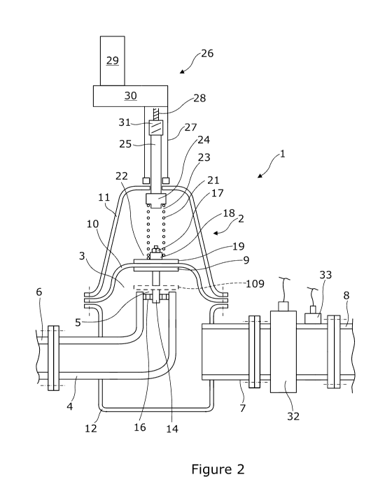
Selon l'invention, un régulateur à ressort comporte un corps contenant une chambre dotée d'une entrée reliée à une conduite principale d'alimentation en eau sous pression. La chambre est reliée à un réseau de canalisations destiné à la distribution locale d'eau. Le régulateur comprend une plaque de régulation de la pression d'écoulement. Un diaphragme est fixé à la plaque et forme un joint d'étanchéité avec des parties supérieure et inférieure du corps. Un ressort de compression dont l'extrémité supérieure vient en butée contre un élément d'entraînement à ressort au niveau de l'extrémité d'un tube d'entraînement d'un dispositif d'asservissement, agit sur la partie supérieure du diaphragme. Une vis, entrainée par un moteur et une boîte de vitesses, est tourillonnée pour permettre un alignement axial dans le tube d'entraînement à l'intérieur du tube fixe. Un élément d'entraînement à ressort comprime le ressort ou relâche la compression. Les canalisations du réseau de distribution local s'étendent en aval de la sortie. Près de la sortie se trouvent un débitmètre et un capteur de pression, tous deux connectés électroniquement à un dispositif de commande ayant un capteur de pression à distance connecté au point le plus éloigné de la tuyauterie.


Abrégé anglais

A spring-loaded regulator has a body containing a chamber with an inlet connecting to a pressurized water main. The chamber connects to a pipe network for local water distribution. The regulator has a flow pressure regulation plate. A diaphragm is fastened to the plate, sealing with upper and lower parts of the body. A compression spring, whose upper end abuts a spring drive member at the end of a servo device's drive tube, acts on top of the diaphragm. A screw, driven by a motor and gearbox, is journalled for axial alignment in the drive tube within the fixed tube. A spring drive member compresses/de-compresses the spring. Downstream from the outlet, the local distribution network's pipework extends. Adjacent the outlet is a flow meter and pressure sensor, both electronically connected to a controller having a remote pressure sensor connected to it at the furthest point of the pipework.

Revendications

Note : Les revendications sont présentées dans la langue officielle dans laquelle elles ont été soumises.


7
CLAIMS:
1. A fluid pressure reducing valve apparatus comprising:
.cndot. a spring loaded regulator having:
.cndot. a body containing a chamber,
.cndot. a liquid supply orifice into the chamber and a liquid outlet from
the
chamber,
.cndot. a regulation plate opposed to the orifice and subject in use to
supply liquid
acting on it,
.cndot. a spring acting to urge the plate towards to the orifice and
.cndot. a diaphragm between the regulation plate and the body to close the
chamber between them and subject in use to regulated pressure in the
chamber
.cndot. a controllable motor drive acting between the body and an end of
the spring
remote from the regulation plate,
.cndot. a flow meter downstream of the outlet and
.cndot. a controller arranged to receive flow data from the flow meter and
to control
the servo motor for withdrawal of the remote end of the spring in accordance
with flow rate measured by the flow meter;
the arrangement being such that in use for increase in demand flow, the
regulator
plate is partially withdrawn to maintain downstream pressure on such increase
and
vice versa.
2. A fluid pressure reducing valve apparatus as claimed in claim 1, wherein
the
apparatus is adapted for reducing the pressure of water.
3. A fluid pressure reducing valve apparatus as claimed in claim 1, wherein
the
apparatus is adapted for reducing the pressure of hydrocarbons fluids both
liquid and
gaseous.
4. A fluid pressure reducing valve apparatus as claimed in claim 1, claim 2 or
claim
3, wherein the controllable motor drive is a servo motor drive.
5. A fluid pressure reducing valve apparatus as claimed in claim 4, wherein
the
controller is adapted for calculation of the server motor action in spring
positioning in
accordance with a substantially linear downstream pressure and flow rate
relationship.

8
6. A fluid pressure reducing valve apparatus as claimed in claim 5, wherein
the
calculation is based on pressure to be achieved in terms of servo positioning
of the
spring.
7. A fluid pressure reducing valve apparatus as claimed in claim 5, wherein
the
calculation is based on servo positioning of the spring alone.
8. A fluid pressure reducing valve apparatus as claimed in claim 5, wherein
the
calculation is based on a lookup table of downstream pressure and flow rate.
9. A fluid pressure reducing valve apparatus as claimed in claim 8, wherein
the
lookup table includes values of pressure to be achieved.
10. A fluid pressure reducing valve apparatus as claimed in claim 8, wherein
the
lookup table includes spring positions in terms of servo revolutions.
11. A fluid pressure reducing valve apparatus as claimed in any preceding
claim,
wherein the regulation plate is provided in abutment with a central region of
the
diaphragm, with a guide rod extending into a centring guide in the orifice.
12. A fluid pressure reducing valve apparatus as claimed in any one of claims
1 to 10,
wherein the regulation plate is provided spaced from the diaphragm, on a guide
rod
extending from the diaphragm into a centring guide in the orifice.
13. A fluid pressure reducing valve apparatus as claimed in any preceding
claim,
wherein the spring is a compression spring acting on the side of the diaphragm
remote
from the orifice.
14. A fluid pressure reducing valve apparatus as claimed in any one of claims
1 to 12,
wherein the spring is a tension spring acting on the side of the diaphragm
near to the
orifice.
15. A fluid pressure reducing valve apparatus as claimed in any preceding
claim,
wherein the a controllable motor drive includes a nut and lead screw device
arranged
to act on the spring at an end remote from diaphragm and actuatable by a motor
of the
drive.
16. A fluid pressure reducing valve apparatus as claimed in any preceding
claim in
combination with a remote pressure sensor for measuring downstream pressure to
be
maintained.

Description

Note : Les descriptions sont présentées dans la langue officielle dans laquelle elles ont été soumises.


CA 03144207 2021-12-17
WO 2021/089986
PCT/GB2020/052750
1
LIQUID PRESSURE REDUCING VALVE
The present invention relates to a liquid pressure reducing valve,
particularly
though not exclusively for water mains.
Loss of water from mains is a problem due to the age of mains pipework and
damage to mains and associated equipment. Many mains are old and have multiple

leaks. Even newer mains can suffer leaks. Leak flow is greatest when the water

pressure is highest, unsurprisingly. However I have noted a simple correlation
to between on the one hand pressure required downstream of a regulator to
maintain a
given minimum pressure at a remote point of a local network, the regulator
being
between a high pressure regional supply and the local network, and on the
other hand
flow in the local network. Both the required regulated pressure and the flow
on the
downstream side of the regulator appear to be normally linearly related.
Despite this
I am aware of no pressure regulators controlled in accordance with flow
through
them, except for the following.
In the prior proposal of GB 2,176,316, there was disclosed, in terms of its
abstract:
Apparatus for controlling the flow of water through a pipe (26) including a
valve (29) and an orifice plate (37) and supplying a water distribution system

comprises a governor (1) actuating a pilot valve (14) in a servo system
controlling the
valve (29). The governor (I) has two diaphragms (5) and 6) linked by a tension

spring (7) the extension of which is determined by the rate offlow through the
orifice
plate (37). The first diaphragm (5) operates a valve member (13) of the pilot
valve
(14) and is subjected to the dfferential pressure caused by flow through the
orifice
plate (37). The second diaphragm (6) is loaded by a compression spring (8) and
its
displacement is dependent upon the control pressure at a tapping (38) in the
pipe
(26).; The movement of the valve member (14) is the combination of the
displacements
of the two diaphragms (5 and 6), and raises the control pressure at tapping
(38) when
demand for water increases.
The object of the present invention is to provide an improved liquid pressure
reducing valve

CA 03144207 2021-12-17
WO 2021/089986
PCT/GB2020/052750
2
According to the invention there is provided a fluid pressure reducing valve
apparatus comprising: =
= a spring loaded regulator having:
= a body containing a chamber,
= a liquid supply orifice into the chamber and a liquid outlet from the
chamber,
= a regulation plate opposed to the orifice and subject in use to supply
liquid
acting on it,
= a spring acting to urge the plate towards to the orifice and
= a diaphragm between the regulation plate and the body to close the
chamber between them and subject in use to regulated pressure in the
chamber
= a controllable motor drive acting between the body and an end of the
spring
remote from the regulation plate,
= a flow meter downstream of the outlet and
= a controller arranged to receive flow data from the flow meter and to
control
the servo motor for withdrawal of the remote end of the spring in accordance
with flow rate measured by the flow meter;
the arrangement being such that in use for increase in demand flow, the
regulator
plate is partially withdrawn to maintain downstream pressure on such increase
and
vice versa.
Preferably the controllable motor drive is a servo motor drive.
The invention is particularly applicable to water mains, where the fluid is
liquid, in particular water. I envisage that the invention to be applicable to

hydrocarbons fluids both liquid and gaseous.
The controller can be adapted for calculation of the server motor action in
spring positioning in accordance with a substantially linear downstream
pressure and
flow rate relationship. The calculation can be based on pressure to be
achieved in
terms of servo positioning of the spring; or on servo positioning of the
spring alone.

CA 03144207 2021-12-17
WO 2021/089986
PCT/GB2020/052750
3
Alternatively it can be adapted for servo motor action in accordance with a
lookup
table of downstream pressure and flow rate. Again the lookup table can include

values of pressure to be achieved, but is preferably includes spring positions
in terms
of servo revolutions.
To help understanding of the invention, a specific embodiment thereof will
now be described by way of example and with reference to the accompanying
drawings, in which:
Figure 1 is Figure 2 of prior proposal GB 2,176,316,
Figure 2 a diagrammatic, cross-sectional, side view of a pressure regulator of
the invention,
Figure 3 is a similar on a smaller scale and including a controller and a line
from a remote pressure sensor,
Figure 4 is a typical plot of pressure required to be applied in a network for
constant remote pressure with varying demand flow and
Figure 5 is a.diagram of a water Main having a regulator of the invention and
many customer supply taps and leaks.
Referring to the drawings, a spring loaded regulator 1 has a body 2 containing
a chamber 3. An inlet 4 opens into the chamber via an inlet orifice 5. The
inlet is
connected to an elevated pressure water main 6. An outlet 7 from the chamber
is
connected to a network 8 of pipes for local distribution of water to
individual
consumers. The regulator has a flow pressure regulation plate 9 arranged
opposite the
inlet orifice 5. A diaphragm 10 is fastened to the plate 9 and radiates from
it to the
body, forming a seal with upper and lower parts 11,12 of the body 2. Thus the
chamber 3 is sealed between the upper and lower parts.
The regulation plate has a guide rod 14 extending down from it into a guide 16

in the inlet orifice 5. The rod extends through both the regulation plate and
the
diaphragm. At its top end it carries a nut 17 bearing on a spring centring
washer 18
and a diaphragm sealing and clamping plate 19. The arrangement keeps the
regulation plate centred over the inlet orifice 5.

CA 03144207 2021-12-17
WO 2021/089986
PCT/GB2020/052750
4
In a variant, a separate regulation plate 109 opposite the orifice is provided
on
the lower rod 14. The diaphragm keeps the plate 9 /109 centred over the
orifice 5.
A compression spring 21 acts at its lower end 22 on the top of the clamping
plate 19. The spring is kept compressed to a greater or lesser extent as
explained
below. Thus it stays located around the centring washer 18. Its upper end 23
abuts a
spring drive member 24 at the end of a drive tube 25 of a servo device 26. The
drive
tube is housed in a fixed tube 27 of the servo device, fast with the upper
part 11 of the
regulator body 2. Remote from the spring a lead screw 28 is journalled for
axial
-- alignment in the drive tube within the fixed tube. A motor 29 and gearbox
30 is
arranged to the drive the lead screw. A nut 31, preferably a recirculating
ball nut, is
fast with the remote end of the drive tube 25, with the latter keyed to the
fixed tube
against rotation. Thus the spring drive member can be advanced to further
compress
the spring or retracted to relieve compression, by respective rotation of the
motor and
-- the lead screw.
Downstream from the outlet 7, the pipework 8 of the local distribution
network extends. In it adjacent the outlet is a flow meter 32 and a pressure
sensor 33.
These are electronically connected to a controller 34. Also connected to the
controller
is a remote pressure sensor 35 at the furthest point 36 of the pipework 8.
Along the pipework, there are various leaks 37, which increase in their flow
rate with pressure and a number of user taps 38 etc. It is these which are the
primary
determinant of the flow at the pressure regulator 1. If it were of the type
permanently
set to a pressure maintaining sufficient pressure at the furthest point 36 in
the
network, the pressure would be such as to aggravate the leaks 37 regardless of
the
user flow at the taps 38.
In this embodiment of the invention, the entire pressure reducing valve
apparatus includes not only the regulator 1 and the flow meter 32, but also
the
controller 38 for controlling the regulator, via the servo motor, in
accordance with
flow measured by the flow regulator and indeed the remote pressure sensor 35,
which
is not strictly necessary for the invention.

CA 03144207 2021-12-17
WO 2021/089986
PCT/GB2020/052750
Many local distribution networks such as the network 8 have been previously
measured and exhibit a pressure / flow characteristic as shown in Figure 4
when the
regulator is set to provide the required furthest point pressure for varying
flows. The
ideal low pressure point 41 for zero flow seldom exists due to leaks. The
practical
5 low pressure point 42 can be measured at night when user demand is
negligible.
Other flow and pressure readings 43 can be made during periods of more and
less
usage by adjusting the regulator to provide the sufficient furthest point
pressure.
In practice, the pressure flow plot is a substantially straight line with a
slope or
gradient and an offset equivalent to the zero flow offset. The plot can be
represented
by the equation:
Pressure required at regulator = Zero flow pressure + measured flow x plot
gradient (in terms of pressure per unit flow).
This is surprising, because it might be expected that adjustment of the
regulator would alter the measured flow. However, this is a second order
effect
because the primary determinant of flow is user usage. The leak flow is small
by
comparison and kept lower than it might be, by keeping the pressure in the
network
lower than it would be, if were set to its value to ensure that its furthest
point
sufficiency at maximum flow. This value results in too much flow and too much
leakage at all other flows.
The spring 21 in the regulator acts against the force exerted by the diaphragm

10, which is subject to the pressure to be regulated, the upstream pressure
force
exerted against the regulation plate 9 being substantially constant and being
small in
comparison with the diaphragm force. Thus shortening of the spring by an
amount
proportional to the change in pressure required can provide this change,
bearing in
mind that only a small movement of the rµbgulation plate is required for a
significant
change in pressure drop at the orifice of the outlet. Thus for practical
purposes, linear
movement of the end of the spring acted on by the servo motor causes a linear
change
in regulated pressure. Accordingly the controller can be set up to move the
spring end
linearly in accordance with the flow.

CA 03144207 2021-12-17
WO 2021/089986
PCT/GB2020/052750
6
If the zero flow pressure and the gradient of the measured flow plot are not
known, the controller can be set up to adjust the regulated pressure
periodically for
different flows to establish the pressures required to achieve the sufficient
furthest
away point pressure. For this connection is made with the remote pressure
sensor 35
.. and the near pressure sensor 33, suitably wirelessly in the former case.
The controller can be provided with a memory adapted to record a map of
pressure and flow as opposed to memorising merely the offset and gradient and
use
this as a look-up table for the pressure to which it should regulate the
downstream
.. pressure as a function of measured flow.
The sensor 33 can be used to fine tune the servo motor control to achieve the
desired pressure in accordance with measured flow.

Dessin représentatif
Une figure unique qui représente un dessin illustrant l'invention.
États administratifs

Pour une meilleure compréhension de l'état de la demande ou brevet qui figure sur cette page, la rubrique Mise en garde , et les descriptions de Brevet , États administratifs , Taxes périodiques et Historique des paiements devraient être consultées.

États administratifs

Titre Date
Date de délivrance prévu Non disponible
(86) Date de dépôt PCT 2020-10-30
(87) Date de publication PCT 2021-05-14
(85) Entrée nationale 2021-12-17
Requête d'examen 2023-03-31

Historique d'abandonnement

Il n'y a pas d'historique d'abandonnement

Taxes périodiques

Dernier paiement au montant de 100,00 $ a été reçu le 2023-10-23


 Montants des taxes pour le maintien en état à venir

Description Date Montant
Prochain paiement si taxe applicable aux petites entités 2024-10-30 50,00 $
Prochain paiement si taxe générale 2024-10-30 125,00 $

Avis : Si le paiement en totalité n'a pas été reçu au plus tard à la date indiquée, une taxe supplémentaire peut être imposée, soit une des taxes suivantes :

  • taxe de rétablissement ;
  • taxe pour paiement en souffrance ; ou
  • taxe additionnelle pour le renversement d'une péremption réputée.

Les taxes sur les brevets sont ajustées au 1er janvier de chaque année. Les montants ci-dessus sont les montants actuels s'ils sont reçus au plus tard le 31 décembre de l'année en cours.
Veuillez vous référer à la page web des taxes sur les brevets de l'OPIC pour voir tous les montants actuels des taxes.

Historique des paiements

Type de taxes Anniversaire Échéance Montant payé Date payée
Le dépôt d'une demande de brevet 2021-12-17 408,00 $ 2021-12-17
Taxe de maintien en état - Demande - nouvelle loi 2 2022-10-31 100,00 $ 2021-12-17
Requête d'examen 2024-10-30 816,00 $ 2023-03-31
Taxe de maintien en état - Demande - nouvelle loi 3 2023-10-30 100,00 $ 2023-10-23
Titulaires au dossier

Les titulaires actuels et antérieures au dossier sont affichés en ordre alphabétique.

Titulaires actuels au dossier
POLYMER TECHNOLOGIES LIMITED
Titulaires antérieures au dossier
S.O.
Les propriétaires antérieurs qui ne figurent pas dans la liste des « Propriétaires au dossier » apparaîtront dans d'autres documents au dossier.
Documents

Pour visionner les fichiers sélectionnés, entrer le code reCAPTCHA :


Pour visualiser une image, cliquer sur un lien dans la colonne description du document. Pour télécharger l'image (les images), cliquer l'une ou plusieurs cases à cocher dans la première colonne et ensuite cliquer sur le bouton "Télécharger sélection en format PDF (archive Zip)" ou le bouton "Télécharger sélection (en un fichier PDF fusionné)".

Liste des documents de brevet publiés et non publiés sur la BDBC .

Si vous avez des difficultés à accéder au contenu, veuillez communiquer avec le Centre de services à la clientèle au 1-866-997-1936, ou envoyer un courriel au Centre de service à la clientèle de l'OPIC.


Description du
Document 
Date
(yyyy-mm-dd) 
Nombre de pages   Taille de l'image (Ko) 
Abrégé 2021-12-17 1 72
Revendications 2021-12-17 2 85
Dessins 2021-12-17 4 107
Description 2021-12-17 6 247
Dessins représentatifs 2021-12-17 1 30
Traité de coopération en matière de brevets (PCT) 2021-12-17 4 153
Traité de coopération en matière de brevets (PCT) 2021-12-17 3 116
Rapport de recherche internationale 2021-12-17 3 79
Demande d'entrée en phase nationale 2021-12-17 8 256
Page couverture 2022-01-31 1 54
Requête d'examen / Ordonnance spéciale 2023-03-31 5 116
Ordonnance spéciale - Verte acceptée 2023-04-17 1 179
Demande d'examen 2023-05-05 5 222
Demande d'examen 2024-01-16 4 180
Modification 2024-02-28 6 121
Correspondance reliée au PCT 2024-04-25 5 160
Modification 2023-08-31 26 844
Abrégé 2023-08-31 1 31
Description 2023-08-31 7 379
Revendications 2023-08-31 3 118
Dessins 2023-08-31 4 111