Note : Les descriptions sont présentées dans la langue officielle dans laquelle elles ont été soumises.
CA 03144560 2021-12-21 2021/005196
PCT/EP2020/069485
- 1 -
HANDY LARGE PROCESSING JUG
Field of the Invention
The field of the invention pertains to machines for
processing a food substance, such as milk or a milk-
containing substance, having a food processing receptacle
that is seizable single-handed. For instance, the machine
is provided with an impeller and/or a thermal management
arrangement.
Background Art
Speciality beverages in which at least a portion is
made up of frothed or heated milk are becoming more and
more popular. The best-known beverage of this type is a
coffee of the cappuccino type. It comprises a liquid
portion consisting of coffee topped by a layer of frothed
milk which, because of its very much lower density,
floats atop the surface of the liquid. In general,
preparing one takes time, manipulation operations and
cleaning.
Milk-based froth can be prepared in a mechanical
stirring appliance. Regular cleaning of the tank of the
appliance needs to be envisaged in order to remove any
solid food residue. In addition, heating the milk has a
tendency to increase the extent to which cooked or burnt
proteins are deposited on and adhere to the surfaces.
US Patent 6,318,247 relates to an appliance for
preparing hot beverages or food with stirring such as hot
chocolate, for example. Other devices for stirring food
products are described in patent documents WO 2004/043213
or DE 196 24 648. Stirring systems with a magnetic
engagement type are described in documents US 2,932,493,
DE 1 131 372, US 4,537,332 and US 6,712,497. DE 89 15 094
relates to a refrigerated pot for dispensing a milk-based
beverage. US Patent 3,356,349 discloses a stirring device
that has a heated tank, magnetic drive means positioned
under the tank for driving a hub located in the middle of
the tank.
CA 03144560 2021-12-21 2021/005196
PCT/EP2020/069485
- 2 -
Fur the r examples of beverage processing appliances
using stirring systems, in particular magnetically driven
stirring systems, are disclosed in WO 2016/202814, WO
2016/202815, WO 2016/202816, WO
2016/202817, WO
2018/108804 and WO 2018/108807 .
An improved appliance for preparing froth from a
milk-based liquid or milk has been proposed in WO
2006/050900, WO 2008/142154, WO
2010/023313, WO
2011/039222, WO 2011/039224 and WO 2017/216133. The
device has: an inner tank for receiving the liquid that
is to be frothed, in which a rotatable stirrer is
positioned; an outer stand holding the tank; drive and
control means which are in a cavity located between the
inner tank and the outer stand, and which communicate
with a switch and electrical connections located on the
outer surface of the stand; and disturbance means to
optimise circulation of the milk during frothing.
Heat can be provided into the processing tank by
using an induction system, e.g. as disclosed in WO
.. 2019/101765.
It has been proposed, as described in WO 2009/074555
and WO 2011/144647, to provide a coffee machine with this
type of milk conditioning tank. In WO 2009/074555 the
upright surface of the processing tank is profiled to
facilitate hand gripping.
An architecture to favour the evacuation of unwanted
heat generated by the operation of electric components of
the milk frothing appliance has been disclosed in WO
2016/202818. As disclosed in WO 2018/108808 and WO
2019/101764, such appliance can also be fitted with one
or more fan coolers.
WO 2017/216133, WO 2019/101765 and PCT/EP19/057841
disclose a beverage processing tank. The beverage can be
heated in the tank. To dispense the processed beverage,
the tank is fitted with a handle that has a connection
member projecting from the tank and a generally upright
elongated gripping part extending above and below the
connection member.
CA 03144560 2021-12-21 2021/005196
PCT/EP2020/069485
- 3 -
There is still a need to improve the handling of
such appliances, especially when they are configured to
process large amounts of liquid food substance.
Summary of the Invention
It is a preferred object of the present invention to
provide a convenient to handle machine for conditioning a
food substance, typically a machine able to handle larger
amounts of food substance.
The invention thus relates to a machine for
processing a liquid food substance, such as milk or a
milk-based substance. The liquid food substance can be
aqueous, e.g. containing coffee and/or chocolate and/or
cacao.
The machine may be a standalone machine, e.g.
directly pluggable to the mains via an electric cord, or
may be integrated in a food processor arranged to process
other food items or to carry out different food
conditioning processes, the food processor itself being
generally pluggable to the mains via an electric cord
whereas the machine is a sub-part of the food processor.
Such a food processor may be a beverage maker, such as a
coffee maker, e.g. a beverage maker configured to prepare
a beverage (such as coffee) from an ingredient capsule.
The machine of the invention may advantageously be
configured to froth and/or heat and/or cool milk and
optionally be associated, as a standalone machine or as
an integrated machine, into a coffee maker. Standalone
machines and integrated associations of milk frothing
machines and coffee makers are for example disclosed in
WO 2006/050900, WO 2008/142154, WO 2009/074555, WO
2010/023312 and WO 2010/023313.
Hence, the machine can be a milk frother which
operates by incorporating finely divided gas bubbles,
e.g. air bubbles, into milk. When the machine is
configured for incorporating gas bubbles into milk, it
may include an operating mode without incorporation of
gas bubbles.
CA 03144560 2021-12-21 2021/005196
PCT/EP2020/069485
- 4 -
The machine of the invention is configured for
processing a liquid food substance, such as milk or a
milk-based substance.
Therefore, the machine includes a tank having a
cavity for containing and processing the liquid food
substance, such as milk or a milk-based substance.
The tank may have an access opening that is covered
by a removable lid, e.g. via a seal. The access opening
may be uncovered or free of any lid. Examples of
removable lids and/or seals are disclosed in WO
2008/142154 and in PCT/EP19/057844.
The removable lid can extend over a rim of the tank
and have a peripheral wall that extends downwardly to
form an outside lid face. The outside lid face may have a
height in the range of 0.5 to 5 cm e.g. in the range of
1.5 to 3.5 cm. The outside lid face may extend flush with
an outside face of the container uncovered by the lid
and/or with an outside face of the base.
The removable lid can have an upright inner wall
that extends downwardly into the cavity along a or the
above mentioned rim of the tank. For instance, the
peripheral wall and/or the upright inner wall has a
sealing member, such as an annular deformable sealing
member e.g. the above mentioned seal, for sealing off the
cavity of the tank. Such sealing member may include at
least one of the following features: the sealing member
has one or more substantially parallel sealing lips, such
as annular lips arranged side-by-side; the sealing member
has a tab for seizing the sealing member; and the sealing
member is removable from the lid, for instance for
cleaning, and mountable on the lid.
The tank can be substantially cup-shaped or bowl-
shaped or cylinder-shaped, the sidewall being
substantially upright and the bottom wall being
substantially flat or curved.
The tank may be mechanically passive. Hence, beyond
the inherent mechanical properties of the materials
making its structure for containing the food substance
and for being integrated or assembled in the machine, the
tank may be free of any mechanically active part such as
CA 03144560 2021-12-21
WO 2021/005196
PCT/EP2020/069485
- 5 -
a motor or movement transformation system which may
require special care for hygiene or cleaning purposes.
The machine has a stirring tool in the cavity for
imparting a mechanical effect on the food substance in
the cavity. The stirring tool, e.g. a passive tool, may
be driven from outside the tank. The stirring tool can be
drivable to rotate in the cavity at a rotational speed in
the range of 300 to 10000 RPM, for instance 500 to 7500
RPM, such as 900 to 5000 RPM, e.g. 1250 to 4250 RPM.
The tank may be electrically passive. Hence, beyond
the inherent electrical properties (e.g. resistive and/or
inductive and/or capacitive properties) of the materials
making its structure for containing the food substance
and for being integratable or assembled in the machine,
the tank may be free of any electric components, in
particular active electric components. The inherent
electrical properties of the tank may however be used in
the processing of the food substance, for instance for
heating and/or cooling the tank that is powered
electrically or electromagnetically from an (active)
source that is external to the tank.
The machine has a base that supports the tank.
The tank may be fixed or integral with the base, or
separable from the base by the user, e.g. for cleaning or
servicing.
By providing a tank which is mechanically and/or
electrically passive (optionally with a lid that is
equally passive), it can easily be cleaned, e.g. in a
dishwater, without any risk of damaging electric and/or
mechanic components, if the tank is separable from the
base.
The same result can be achieved when the tank is
inseparable (by the user) from the base that is provided
with a control cavity, e.g. containing mechanical and/or
electric control active constituents, such as actuators
and signal processing units, which control cavity has no
movable access panel sealed off by a rubber, silicone or
like seal that is exposed to early wear, especially when
exposed to detergents or soaps used for cleaning. Hence,
the same result may be achieved, if the base contains
CA 03144560 2021-12-21
WO 2021/005196
PCT/EP2020/069485
- 6 -
active components that are contained in an inaccessible
confinement control cavity, the base being for instance
entirely moulded and/or welded around such a confinement
cavity so that the cavity is completely sunk in the
base's structure and separate from the environment
outside the base with no access from the outside without
destroying the base. In such circumstances, the base may
contain in such confined inaccessible cavity an active
device, e.g. an RFID-type device or the like, and still
be suitable for cleaning in a dishwasher.
The base has an upright outside gripping surface,
e.g. a textured or striated or corrugated or undulated or
ruled or even surface to facilitate hand gripping. The
outside gripping surface is located under the tank and is
seizable by an adult human hand, such that the base with
the supported tank can be carried and displaced single-
handed by seizure of the upright outside gripping
surface.
By providing a base with an outside gripping surface
extending horizontally around at least a substantial part
of the base, the machine does not need to be fitted with
an elongated handle protruding from an outside face, for
instance of the variety disclosed in WO 2006/050900 or in
PCT/EP19/057841.
The tank of the invention extends horizontally
beyond the outside gripping surface.
By allowing the tank to extend beyond the outside
gripping surface, the volume of the tank's cavity may be
correspondingly increased in a lateral fashion without
affecting the ability of the gripping surface to be
gripped by the adult human hand, i.e. the gripping
surface is not increased with the tank's cavity volume as
in prior art designs. Such a configuration permits the
processing of an increased volume of liquid food
substance, laterally rather than in elevation, which is
advantageous for instance when air is to be incorporated
into the liquid food substance during processing (e.g. to
froth the liquid food substance).
The lateral extension of the tank beyond the outside
gripping surface of the base may also serve as a support
CA 03144560 2021-12-21
WO 2021/005196
PCT/EP2020/069485
- 7 -
surface on the gripping human hand to improve seizure of
the machine single handed.
The outside gripping surface may be at least
substantially vertical, such as vertical or inclined
thereto by an angle of less than 15 deg., for instance
less than 10 deg., e.g. less than 5 deg., for example
less than 2.5 deg.
The tank can have an outer horizontal tank
perimeter.
The tank can extend horizontally beyond the outside
gripping surface over a predominant part of its tank
perimeter, e.g. over more than 50 or more than 75% of its
perimeter, such as over substantially the entire
perimeter, e.g. above 90 or 95% of the perimeter.
The perimeter may have a circumference in the range
of 15 to 70 cm, for instance 20 to 60 cm, such as 25 to
50 cm, e.g. 30 to 40 cm.
The tank may have an upright outer tank surface and
the cavity may have a height, the outer horizontal
perimeter extending along the outer tank surface, the
outer tank surface being horizontally located beyond the
outside gripping surface over substantially its entire
tank perimeter over substantially the entire cavity
height. For instance, the upright outer tank surface is
horizontally located beyond the outside gripping surface
by a distance in the range of 0.5 to 10 cm, for instance
1 to 7 cm, such as 1.5 to 5 cm, e.g. 2 to 4 cm.
The upright outer tank surface may be at least
substantially vertical, e.g. vertical or inclined thereto
by an angle of less than 15 deg. For instance, the
upright outer tank surface is inclined to the vertical by
an angle of less than 10 deg., such as less than 5 deg.,
e.g. less than 2.5 deg.
The machine typically includes an outside housing.
The housing may form the upright outside gripping
surface. The housing may extend upright along at least
part of the outer tank surface.
For instance, the housing has a substantially
horizontal and/or inclined, e.g. straight or curved,
CA 03144560 2021-12-21
WO 2021/005196
PCT/EP2020/069485
- 8 -
intermediate portion extending from a top of the upright
outside gripping surface to a bottom of the upright outer
tank surface. For example, such inclined intermediate
portion has an inclination to a horizontal direction in
the range of 15 to 75 deg., such as 20 to 70 deg., e.g.
40 to 60 deg.
The machine may have a foot that has a bottom side
configured to be placed on a substantially horizontal
external support surface, such as a surface formed by a
table or a shelf, during processing of the liquid food
substance, and to support the base during such
processing. For instance, the foot is assembled to or
fixed to or integral with the base.
The base can be removably mounted to the foot. The
base and the foot may have a connection.
The connection may be configured to inhibit or
prevent relative pivoting of the base and the foot about
an axis extending along the external support surface
during processing. For instance, the connection is
mechanical and/or magnetic.
The connection can be configured to conduct electric
power from the foot into the base. For instance, the foot
has an electric cord for connection to an external power
supply, such as to the mains.
The connection may be configured to be connectable
in a plug and socket fashion. For instance, the
connection has a plug part of the foot and a socket part
of the base, or vice versa.
The foot may extend horizontally beyond the outside
gripping surface, e.g. the foot extending horizontally up
to or beyond the tank. For instance, the foot extends
horizontally beyond the outside gripping surface by a
distance in the range of 0.5 to 15 cm, for example 1 to
10 cm, such as 1.5 to 7 cm, e.g. 2 to 3 cm.
Providing a large foot, e.g. larger than the
gripping surface, may increase the stability of the
machine during processing on the external processing
surface.
CA 03144560 2021-12-21
WO 2021/005196
PCT/EP2020/069485
- 9 -
The upright outside gripping surface can have a
height along which the surface is seizable by the adult
human hand for carrying and supporting single-handed the
base and the tank, the height being of at least 3 cm, for
instance in the range of 4 to 20 cm, such as 5 to 16 cm,
e.g. 6 to 12 cm.
The machine may include, for instance within the
base, an actuator that is connected or connectable to the
stirring tool. The actuator may be magnetically coupled
to the stirring tool, e.g. via a tank side wall and/or a
bottom wall and/or top wall.
Actuators e.g. motors, control units, user-
interfaces, AC/DC converters can all be comprised in the
base.
The machine can comprise, for instance within the
base, a thermal conditioner that is associated with a
tank side wall and/or a bottom wall configured to emit
thermal energy into and/or absorb thermal energy from the
cavity. For instance, the thermal conditioner comprises
at least one of: a resistor, e.g. a thick film resistor;
an induction (e.g. cooperating with the tank side and/or
bottom wall to produce inductive heat); a thermocouple;
and a heat pump.
Example of suitable thermal conditioners are
disclosed in WO 2006/050900, WO 2008/142154, WO
2010/023312, WO 2010/023313 and WO 2019/101765.
The machine may include, for instance within the
base, a control unit, such as a processor and/or a
controller, for controlling at least one of a or the
above stirring tool actuator and a or the above wall-
associated thermal conditioner. For instance, the control
unit includes a user-interface, such as a user-interface
at a or the above outside housing.
The cavity may have a volume that is greater than
200 ml, for instance in the range of 250 to 1250, such as
in the range 300 to 1000 ml, e.g. in the range of 450 to
850 ml or 500 to 700 ml.
The cavity or an upright part of the stirring tool
may be associated with or may include an indication
arrangement for assisting an appropriate filling of the
CA 03144560 2021-12-21
WO 2021/005196
PCT/EP2020/069485
- 10 -
cavity with liquid food substance prior to its processing
in the cavity. For instance, the indication arrangement
has an indicator, e.g. a high indicator, for a maximum
level for thermally conditioning such liquid food
substance without frothing and/or an indicator, e.g. a
low indicator, for a maximum level for frothing such
liquid food substance with or without thermal
conditioning. The indicator may include at least one of:
a verbal sign; a sign, e.g. a pictogram, of a
corresponding stirring tool, such as a tool for frothing
or a tool for thermal conditioning; and a level sign.
The stirring tool may include an impelling device
for frothing the liquid food substance, such as an
impelling device comprising a helicoidal spring and/or an
undulated plate and/or a plurality of radial frothing
wings.
The stirring tool may incorporate a (e.g. non-
frothing) homogenising device for homogenizing the liquid
food substance during thermal conditioning thereof, such
as a homogenising device comprising at least one radial
homogenising arm, e.g. 2, 3 or 4 radial homogenising
arms.
The stirring tool may have a or the above mentioned
upright extending elongated part. For instance such part
is topped with a radial protruding element e.g. a ball.
The stirring tool may include an upright arched part
such as an arched part located above at least one of: a
or the above mentioned impelling device and a or the
above mentioned homogenising device. For instance, the
upright arched part is located below a or the above
mentioned upright extending elongated part.
The stirring tool may have a connection part for
connection with a connection part of the tank and/or of
the base to position the stirring tool in the tank. For
instance, such connection parts form a plug and socket
arrangement and/or magnetic connecting parts. The
connection parts may be configured to position the
stirring tool on a central upright axis in the cavity or
in parallel to such axis.
CA 03144560 2021-12-21 2021/005196
PCT/EP2020/069485
- 11 -
The cavity and the stirring tool may be configured
for (central) symmetric processing of the liquid food
substance or for asymmetric processing. For instance, a
flow perturbator is used to promote homogeneisation of
the food substance during processing, e.g. by setting the
stirring tool off-set relative to a central upright axis
and/or by arranging obstacles in the cavity that
interfere with a flow of the food substance during
processing.
The stirring tool and its integration into the
machine may be of the type disclosed in WO 2006/050900,
WO 2008/142154, WO 2016/202814, WO 2016/202815, WO
2016/202816, WO 2016/202817, WO 2018/108804 and WO
2018/108807.
The machine may have a or the above mentioned
central upright axis along which at least one of the
tank, the cavity, the base and a or the above mentioned
foot extends. For instance, at least one of the tank, the
cavity, the base and, if present, the foot has a shape of
revolution about the central upright axis, such as a
cylindrical and/or conical shape and/or spherical shape.
Examples of such shapes are disclosed in WO
2008/142154 and PCT/EP19/060854.
When reference is made in the present description to
an orientation or position relative to the machine or
parts thereof, e.g. "above" or "below" or "vertical" or
"horizontal", the orientation or position takes as a
reference the position and orientation of the machine in
operation to process the liquid food substance in the
tank unless specified otherwise.
Brief Description of the Drawings
The invention will now be described with reference
to the schematic drawings, wherein:
- Figure 1 is a perspective side view of a machine
having a tank, a base and a foot according to the
invention;
CA 03144560 2021-12-21
WO 2021/005196
PCT/EP2020/069485
- 12 -
- Figure 2 is a perspective side view of the machine of
Fig. 1 in which the tank and the base have been
separated from the foot; and
- Figure 3 is a cross-sectional perspective view of the
machine shown in Fig. 1.
Detailed description
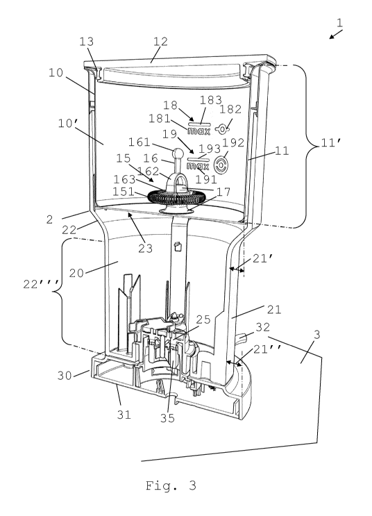
An exemplary embodiment of a machine 1 according to
the invention is illustrated in Figs 1 to 3.
Machine 1 has a tank 10 with a cavity 10' for
containing and processing a liquid food substance, such
as milk or a milk-based substance.
Machine 1 includes a stirring tool 15 in cavity 10'
for imparting a mechanical effect on the food substance
in cavity 10', e.g. a stirring tool 15 driven from
outside tank 10. Stirring tool 15 may be drivable to
rotate in cavity 10' at a rotational speed in the range
of 300 to 10000 RPM, for instance 500 to 7500 RPM, such
as 900 to 5000 RPM, e.g. 1250 to 4250 RPM.
Machine 1 has a base 20 that supports tank 10. Base
20 has an upright outside gripping surface 21, e.g. a
textured or striated or corrugated or undulated or ruled
or even surface 21 to facilitate hand gripping, located
under tank 10 and seizable by an adult human hand such
that base 20 with supported tank 10 can be carried and
displaced single-handed by seizure of the upright outside
gripping surface 21.
Tank 10 may have an access opening, e.g. a top
access opening, that is covered by a removable lid 12
.. e.g. via a seal 13.
Tank 10 extends horizontally beyond outside gripping
surface 21.
Outside gripping surface 21 may be at least
substantially vertical, for instance vertical or inclined
thereto by an angle of less than 15 deg., such as less
than 10 deg., for example less than 5 deg., e.g. less
than 2.5 deg.
Tank 10 may have an outer horizontal tank perimeter.
CA 03144560 2021-12-21 2021/005196
PCT/EP2020/069485
- 13 -
Tank 10 may extend horizontally beyond outside
gripping surface 21 over a predominant part of its tank
perimeter, e.g. over more than 50 or more than 75% of its
perimeter, such as over substantially the entire
perimeter, e.g. above 90 or 95% of the perimeter.
The perimeter may have a circumference in the range
of 15 to 70 cm, for instance 20 to 60 cm, such as 25 to
50 cm, e.g. 30 to 40 cm.
Tank 10 can have an upright outer tank surface 11
and cavity 10' may have a height 11'. The outer
horizontal perimeter may extend along outer tank surface
11, outer tank surface 11 being located horizontally
beyond outside gripping surface 21 over substantially its
entire tank perimeter over substantially the entire
cavity height 11'. For instance, upright outer tank
surface 11 is located horizontally beyond outside
gripping surface 21 by a distance 21' in the range of 0.5
to 10 cm, such as 1 to 7 cm, e.g. 1.5 to 5 cm, for
example 2 to 4 cm.
Upright outer tank surface 11 may be at least
substantially vertical, for instance vertical or inclined
thereto by an angle of less than 15 deg., such as less
than 10 deg., e.g. less than 5 deg., for example less
than 2.5 deg.
Machine 1 may include an outside housing 2 that
forms the upright outside gripping surface 21, outside
housing 2 extending upright along at least part of the
outer tank surface 11. For instance, housing 2 includes a
substantially horizontal and/or inclined intermediate
portion 22, e.g. a straight or curved portion, extending
from a top of the upright outside gripping surface 21 to
a bottom of the upright outer tank surface 11, such as an
inclined intermediate portion 22 having an inclination to
a horizontal direction in the range of 15 to 75 deg.,
such as 20 to 70 deg., e.g. 40 to 60 deg.
Machine 1 can have a foot 30 that has a bottom side
31 configured to be placed on a substantially horizontal
external support surface 3, such as a surface 3 formed by
a table or a shelf, during processing of the liquid food
substance, and to support base 20 during such processing.
CA 03144560 2021-12-21 2021/005196
PCT/EP2020/069485
- 14 -
For instance, foot 30 is assembled to or fixed to or
integral with base 20.
Base 20 may be removably mounted to foot 30. Base 20
and foot 30 can have a connection 25,35.
Connection 25,35 may be configured to inhibit or
prevent relative pivoting of base 20 and foot 30 about an
axis extending along external support surface 3 during
such processing. For instance, connection 25,35 is
mechanical and/or magnetic.
Connection 25,35 can be configured to conduct
electric power from foot 30 into base 20. For instance,
base 30 has an electric cord 32 for connection to an
external power supply, such as to the mains.
Connection 25,35 may be configured to be connectable
in a plug 35 and socket 25 fashion. For instance,
connection 25,35 having a plug 35 part of foot 30 and a
socket 25 part of base 20, or vice versa.
Foot 30 may extend horizontally beyond the outside
gripping surface 21, e.g. foot 30 extending horizontally
up to or beyond tank 10. For instance, foot 30 extends
horizontally beyond outside gripping surface 21 by a
distance 21" in the range of 0.5 to 15 cm, such as 1 to
10 cm, e.g. 1.5 to 7 cm, for example 2 to 3 cm.
Upright outside gripping surface 21 has a height
21"' along which surface 21 is seizable by the above
mentioned human hand for carrying and supporting single-
handed base 20 and tank 10, the height being of at least
3 cm, for instance in the range of 4 to 20 cm, such as 5
to 16 cm, e.g. 6 to 12 cm.
Machine 1 may include, for instance within base 20,
an actuator that is connected or connectable to stirring
tool 15. For instance, the actuator is magnetically
coupled to stirring tool 15, e.g. via a tank side wall
and/or a bottom wall and/or top wall.
Machine 1 may include, for instance within base 20,
a thermal conditioner 23 that is associated with a tank
side wall and/or a bottom wall configured to emit thermal
energy into and/or absorb thermal energy from cavity 10'.
For instance, the thermal conditioner comprises at least
CA 03144560 2021-12-21 2021/005196
PCT/EP2020/069485
- 15 -
one of: a resistor, e.g. a thick film resistor 23; an
induction (e.g. cooperating with the tank side and/or
bottom wall to produce inductive heat); a thermocouple;
and a heat pump.
Machine 1 can include, for instance within base 20,
a control unit, such as a processor and/or a controller,
for controlling at least one of a or the above mentioned
stirring tool actuator and a or the above mentioned wall-
associated thermal conditioner 23. The control unit may
have a user-interface 26, such as an interface 26 at a or
the above mentioned outside housing 2.
Cavity 10' may have a volume that is greater than
200 ml, for instance in the range of 250 to 1250, such as
in the range 300 to 1000 ml, e.g. in the range of 450 to
850 ml or 500 to 700 ml.
Cavity 10' or an upright part 16 of stirring tool 15
may be associated with or may include an indication
arrangement 18,19 for assisting an appropriate filling of
cavity 10' with liquid food substance prior to its
processing in cavity 10'. For instance, the indication
arrangement includes an indicator 18, e.g. a high
indicator 18, for a maximum level for thermally
conditioning the liquid food substance without frothing
and/or an indicator 19, e.g. a low indicator 19, for a
maximum level for frothing the liquid food substance with
or without thermal conditioning. The indicator may
comprise at least one of: a verbal sign 181,191; a sign,
e.g. a pictogram 182,192, of a corresponding stirring
tool; and a level sign 183,193.
Stirring tool 15 may include an impelling device
151,192 for frothing the liquid food substance. For
instance, the impelling device includes a helicoidal
spring and/or an undulated plate and/or a plurality of
radial frothing wings.
Stirring tool 15 can include a homogenising device
182 for homogenizing the liquid food substance during
thermal conditioning thereof, such as a homogenising
device comprising at least one radial homogenising arm,
e.g. 2, 3 or 4 radial homogenising arms.
CA 03144560 2021-12-21
WO 2021/005196
PCT/EP2020/069485
- 16 -
Stirring tool 15 may have a or the above mentioned
upright extending elongated part 16. Part 16 can be
topped with a radial protruding element 161, e.g. a ball.
Stirring tool 15 can have an upright arched part 162
such as an arched part located above at least one of a or
the above mentioned impelling device 151,192 and a or the
above mentioned homogenising device 182. For instance,
the upright arched part 162 is located below a or the
above mentioned upright extending elongated part 16.
Stirring tool 15 may incorporate a connection part
163 for connection with a connection part 17 of tank 10
and/or of base 20 to position stirring tool 15 in tank
10, such as connection parts 163,17 forming a plug and
socket arrangement and/or magnetic connecting parts. For
instance, connection parts 163,17 are configured to
position stirring tool 15 on a central upright axis 1' in
cavity 10' or in parallel to such axis 1'.
Machine 1 may have a or the above mentioned central
upright axis 1' along which at least one of tank 10,
cavity 10', base 20 and (when present) a or the above
mentioned foot 30 extends. At least one of tank 10,
cavity 10', base 20 and, if present, foot 30 can have a
shape of revolution about central upright axis 1' such as
a cylindrical and/or conical shape and/or spherical
shape.