Sélection de la langue

Search

Sommaire du brevet 3164675 

Énoncé de désistement de responsabilité concernant l'information provenant de tiers

Une partie des informations de ce site Web a été fournie par des sources externes. Le gouvernement du Canada n'assume aucune responsabilité concernant la précision, l'actualité ou la fiabilité des informations fournies par les sources externes. Les utilisateurs qui désirent employer cette information devraient consulter directement la source des informations. Le contenu fourni par les sources externes n'est pas assujetti aux exigences sur les langues officielles, la protection des renseignements personnels et l'accessibilité.

Disponibilité de l'Abrégé et des Revendications

L'apparition de différences dans le texte et l'image des Revendications et de l'Abrégé dépend du moment auquel le document est publié. Les textes des Revendications et de l'Abrégé sont affichés :

  • lorsque la demande peut être examinée par le public;
  • lorsque le brevet est émis (délivrance).
(12) Demande de brevet: (11) CA 3164675
(54) Titre français: TURBINE EOLIENNE AVEC AXE VERTICAL DE ROTATION DU ROTOR
(54) Titre anglais: VERTICAL-AXIS WIND TURBINE
Statut: Rapport envoyé
Données bibliographiques
(51) Classification internationale des brevets (CIB):
  • F03D 3/04 (2006.01)
  • F03D 3/06 (2006.01)
(72) Inventeurs :
  • LEOSHKO, ANATOLIJ VIKTOROVICH (Fédération de Russie)
(73) Titulaires :
  • LEOSHKO, ANATOLIJ VIKTOROVICH (Fédération de Russie)
(71) Demandeurs :
  • LEOSHKO, ANATOLIJ VIKTOROVICH (Fédération de Russie)
(74) Agent: SMART & BIGGAR LP
(74) Co-agent:
(45) Délivré:
(86) Date de dépôt PCT: 2019-12-16
(87) Mise à la disponibilité du public: 2021-06-24
Requête d'examen: 2022-06-13
Licence disponible: S.O.
(25) Langue des documents déposés: Anglais

Traité de coopération en matière de brevets (PCT): Oui
(86) Numéro de la demande PCT: PCT/RU2019/000952
(87) Numéro de publication internationale PCT: WO2021/125994
(85) Entrée nationale: 2022-06-13

(30) Données de priorité de la demande: S.O.

Abrégés

Abrégé français

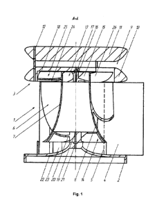
L'invention se rapporte la production d'énergie éolienne. Cette turbine éolienne comprend un rotor et un stator disposés coaxialement comportant des bases inférieure et supérieure connectées entre elles par des pales verticales de guidage de stator. Sur la base inférieure se trouve un concentrateur avec des pales, tandis qu'un diffuseur est disposé au-dessus du stator. Les demi-axes inférieur et supérieur et de rotation du rotor sont disposés sur des supports inférieur et supérieur. Le corps du rotor se présente sous forme d'un cône tronqué creux se rétrécissant vers le haut avec une surface curviligne. Les pales du rotor sont curvilignes, et ont de préférence une surface hyperboloïde. Des ailettes supérieure et inférieure sont fixées dans le corps du rotor. La cavité du disque inférieur du diffuseur comprend en outre un ventilateur de rotor dont les pales courbent la partie supérieure de la surface externe du corps du rotor. Toute la structure permet de générer un mouvement de flux d'air accru dans la turbine éolienne , y compris dans les zones sans vent, grâce à l'accélération du flux d'air par le concentrateur, les ailettes internes du rotor, les pales du rotor et la création d'une raréfaction de l'air par le ventilateur et le diffuseur.


Abrégé anglais

The invention relates to wind energy engineering. A wind turbine comprises a rotor and, mounted coaxially therewith, a stator having a lower base and an upper base that are interconnected by vertical guide blades of the stator. A concentrator with blades is mounted on the lower base, and a diffuser is mounted above the stator. A lower rotary half-shaft and an upper rotary half-shaft of the rotor are mounted in a lower bearing and an upper bearing respectively. The housing of the rotor is in the form of a hollow upwardly tapering truncated cone having a curvilinear surface. The blades of the rotor have a curvilinear, preferably hyperbolic, surface. An upper impeller and a lower impeller are fastened inside the rotor housing. A rotor fan is additionally mounted in a cavity in a lower disc of the diffuser, the blades of said fan enveloping the upper part of the outer surface of the rotor housing. The entire structure causes the movement of an increased flow of air into the wind turbine, including in the wind shadow region, by virtue of the acceleration of the flow of air by the concentrator, the internal rotor impellers and the rotor blades and the evacuation of the air by the fan and the diffuser.

Revendications

Note : Les revendications sont présentées dans la langue officielle dans laquelle elles ont été soumises.


Claims
1. A wind turbine with a vertical axis of rotor rotation, comprising a stator
with lower
and upper bases interconnected by vertical guide vanes of the stator, a rotor
body made
in the form of a hollow truncated cone tapering upward, rotor blades installed
on an outer
surface of the rotor body, upper and lower half-axles of rotor rotation
installed in upper
and lower supports respectively, an upper cross-piece, an upper impeller, a
confuser with
blades installed on the lower base, characterized in that the upper impeller
is secured
inside an upper part of the rotor body, a diffuser is installed above the
stator and is made
in the form of two spaced biconvex discs, a lower disc of the diffuser being
rigidly
connected to an upper disc of the diffuser, while serving as the upper base of
the stator,
the stator vanes have a curved surface and are oriented outward, the rotor
body has a
curved surface with the upper part thereof being secured to the upper half-
axle of rotation
of the rotor with the help of the upper impeller blades, the upper support is
secured to the
upper base with the help of the upper cross-piece, a lower part of the rotor
body comprises
a lower impeller, the blades of which are used to connect the rotor body with
the lower
half-axle of rotation of the rotor, the lower support of which is secured at
the top of the
confuser, a cavity of the lower disc of the diffuser additionally comprises a
rotor fan,
blades of which are wrapped around the upper part of the outer surface of the
rotor body,
while a blades spacing of the upper impeller is selected to be greater than a
blades
spacing of the fan.
2. The wind turbine according to claim 1, characterized in that the surface of
the
rotor body has a hyperbolic shape.
3. The wind turbine according to claim 1, characterized in that a surface of
the rotor
blade has a hyperbolic shape.
4. The wind turbine according to claim 1, characterized in that the stator
vane is
configured to enable a change in an angle of inclination relative to the
vertical axis of the
stator.
7

Description

Note : Les descriptions sont présentées dans la langue officielle dans laquelle elles ont été soumises.


CA 03164675 2022-06-13
PCT/RU2019/000952
VERTICAL-AXIS WIND TURBINE
Field of the Invention
The invention relates to wind energy, and specifically, to wind motors having
a
vertical axis of rotation of the rotor relative to the horizon, and can be
used to convert the
energy of the air flow into a rotary motion, transmitted to an electric
generator, a pump,
or a different rotating mechanism.
Prior art
A wind turbine is known, which comprises a rotor placed vertically with the
possibility of rotation inside a housing and provided with blades [patent DE
3636248, IPC
FO3D 9/00, publ. 05.05.1988]. In the known system, the wind turbine is
installed inside a
pipe and operates in an upward flow of air using a chimney effect.
Another known wind turbine [patent RU 2286477, IPC FO3D 1/02, publ.
27.10.2006] comprises a rotor placed inside a stationary body (stator) with
the possibility
of rotation therewithin. The rotor consists of a shaft with radial-type
turbine blades
installed vertically along the circumference at a given distance from the
center and
attached to the rotor shaft by means of brackets (cross-pieces). The stator is
made in the
form of a guiding apparatus, consisting of vertically arranged guide vanes
mounted at an
acute angle to the outer edge of the radial-type turbine blades, which form
external wind
flow channels located tangentially with respect to an inner circumference of
the system.
A lower part of the rotor is made in the form of an axial turbine. The shaft
is equipped with
axial rotor blades designed to operate in the flow of air coming out of the
guide vanes.
Additional guide vanes are installed in the lower part of the body and are
arranged radially
inside a shell. A lower end of the rotor rests on a fairing, which is rigidly
attached to the
ends of the vanes of the guiding apparatus. An upper part of the shell is
fastened to the
body, while a lower part is secured to an upper part of the hollow body
(upward-pull pipe)
with a confuser installed thereon. Air supply windows are arranged in the
lower part of the
hollow body.
1
Date Recue/Date Received 2022-06-13

CA 03164675 2022-06-13
PCT/RU2019/000952
The wind turbine system according to the patent RU 2286477 (2006) operates by
using the energy of horizontal wind flows, as well as the energy of upward
flows
developing in the hollow body provided with the confuser. However, in this
design, the
upward flows of air are not picked up by the horizontal ones. Instead, they
partially block
such horizontal flows and slow them down. A chaotic uncontrolled mixing of two
practically perpendicular flows results in the formation of a significant and
uncontrolled
turbulence in the upper zone, which therefore reduces the system efficiency.
This
"counteraction" increases as the force of the horizontal wind flows becomes
greater.
An increase in performance efficiency of a wind turbine is achieved in a wind
turbine system [patent RU 2488019, I PC FO3D 3/06, FO3D 3/04, publ.
20.07.2013], which
comprises a stator with upper and lower bases interconnected by vertical
inward-oriented
guide vanes. A rotor provided with longitudinal blades is placed in the
stator. A body of
the rotor is made in the form of a hollow cone tapering upward. Rotor blades
are installed
on its outer surface and are oriented at an angle to an axis of symmetry of
the rotor. Plate-
like cross-pieces are installed in an inner cavity of the rotor, connecting it
with upper and
lower half-axles of rotation. The lower base of the stator is configured to
allow air to enter
the rotor. The upper base of the stator has a conical part directed and
tapering towards
the lower base, and is provided with an axial opening, a diameter of which is
larger than
an upper diameter of the rotor cone, so that an annular gap is formed between
them. An
additional impeller is installed on the upper half-axle of the rotor extending
into the conical
part of the upper base of the stator. The lower half-axle of the rotor is
mounted on the
lower base of the stator. The upper half-axle is connected to the upper base
by means of
radial ribs installed inside the conical part of the upper base. A lower
confuser with the
blades attached thereto is installed on the lower base.
The wind turbine system according to patent RU 2488019 (2013) has following
disadvantages, which reduce its performance efficiency.
The conical part of the upper base of the stator interferes with the operation
of the
entire system by shielding a low-pressure zone created under the upper
impeller from the
outer blades of the rotor. A rather small diameter of the upper impeller
reduces the velocity
2
Date Recue/Date Received 2022-06-13

CA 03164675 2022-06-13
PCT/RU2019/000952
of the upward flow. In addition, the system is not protected from atmospheric
precipitations.
The objective of the invention is to increase the performance efficiency of
the wind
turbine having a vertical axis of rotation of the rotor without changing the
geometric
dimensions.
The technical result consists in increasing the power of the wind turbine by
creating
an enhanced air flow inside thereof.
Disclosure of the Invention
The objective is achieved by the fact that in a wind turbine with a vertical
axis of
rotation of the rotor, which comprises a stator with lower and upper bases
interconnected
by vertical guide vanes of the stator, a rotor body made in the form of a
hollow truncated
cone tapering upward, rotor blades installed on an outer surface of the rotor
body, upper
and lower half-axes of rotation of the rotor installed in upper and lower
supports,
respectively, an upper cross-piece, an upper impeller, a lower confuser with
blades,
wherein, according to the invention, the upper impeller is secured inside an
upper part of
the rotor body, a diffuser is installed above the stator and is made in the
form of two
spaced biconvex discs, a lower disc of the diffuser being rigidly connected to
an upper
disc of the diffuser, while serving as the upper base of the stator, the
stator vanes have a
curved surface and are oriented outward, the rotor body has a curved surface
with the
upper part thereof being secured to the upper half-axle of rotation of the
rotor with the
help of the upper impeller blades, the upper support is secured to the upper
base with the
help of the upper cross-piece, a lower part of the rotor body comprises a
lower impeller,
the blades of which are used to connect the rotor body with the lower half-
axle of rotation
of the rotor, the lower support of which is secured at the top of the
confuser, a cavity of
the lower disc of the diffuser additionally comprises a rotor fan, blades of
which are
wrapped around the upper part of the outer surface of the rotor body, while a
blades
spacing of the upper impeller is selected to be greater than a blades spacing
of the fan.
3
Date Recue/Date Received 2022-06-13

CA 03164675 2022-06-13
PCT/RU2019/000952
Preferably, the surface of the rotor body and the rotor blades have a
hyperbolic
shape.
In addition, the stator vanes are configured to enable a change in an angle of

inclination relative to the vertical axis of the stator.
An increase in power of the wind turbine is achieved by the fact that an
upward
vortex flow is created inside and outside the rotor, which redirects the
horizontal wind
flows inside the system, including those in a wind shadow area, into a
vertical flow with a
swirling effect.
Embodiments of the Invention
The invention is illustrated by the drawings, in which:
Fig. 1 shows a longitudinal axial cross-section (A-A in Fig. 3);
Fig. 2 shows a frontal view;
Fig. 3 shows a top view;
Fig. 4 shows a cross-section (B-B in Fig. 2);
Fig. 5 shows a cross-section (C-C in Fig. 2).
A wind turbine with a vertical axis of rotation of the rotor comprises a
stationary
stator 1 provided with a lower base 2 and an upper base 3. The bases 2 and 3
are
interconnected by vertical guide vanes 4 of the stator, oriented outward and
configured
to rotate relative to an axis 5. A rotor 6 is arranged inside the stator 1 and
has a common
axis of symmetry therewith. A rotor body 7 is made in the form of a hollow
cone tapering
upward, which has a curved surface. It is preferable that the surface of the
rotor body has
a hyperbolic shape.
Longitudinal blades 8 are installed on an outer surface of the rotor body 7
and are
made in the form of curved ribs. The blades 8 are oriented at an angle to the
axis of
4
Date Recue/Date Received 2022-06-13

CA 03164675 2022-06-13
PCT/RU2019/000952
symmetry of the rotor. It is preferable that the surface of the rotor blades
has a hyperbolic
shape.
A diffuser 9 is installed above the stator 1 and is made in the form of two
spaced
biconvex discs, a lower disc 10 of which being rigidly connected to an upper
disc 11 and
serving as the upper base 2 of the stator. The connection between the diffuser
discs can
be achieved, for example, by using studs 12. The distance between the diffuser
discs is
selected to provide lower air pressure above the upper impeller of the rotor.
Upper 13 and lower 14 impellers of the rotor are secured inside the rotor body
7.
Blades 15 of the upper impeller are used to secure the upper part of the rotor
6 to an
upper half-axle of rotation 16 of the rotor, an upper support 17 of which is
attached to the
upper base 2 by means of an upper cross-piece 18. Blades 20 of the lower
impeller 14 of
the rotor are used to connect the rotor 6 with a lower half-axle of rotation
19. A lower
support 21 of the rotor is secured at the top of a confuser 22 provided with
blades 23.
A cavity 24 of the lower disc 10 of the diffuser additionally comprises a
rotor fan
25, blades 26 of which are wrapped around the upper part of the outer surface
of the rotor
body 7.
A blade spacing of the upper impeller 13 is selected to be greater than a
blade
spacing of the fan 25 in order to equalize the flow velocities inside and
outside the rotor
body due to different angular velocities of the blades in the center of the
rotor and the
periphery thereof.
The transmission of the rotary motion of the rotor, for example, to an
electric
generator or a pump, is realized by means of the lower half-axle.
The wind turbine with a vertical axis of rotation of the rotor operates as
follows.
A horizontal air flow hits the stator vanes 4. A part of the flow impacting
the outer
parts of the stator vanes is deflected outward by the vanes to bypass the
rotor 6. Another
part of the air flow impacts the inner surfaces of the stator vanes 4, becomes
accelerated
by them and impacts the rotor blades 8. In this case, due to the curvilinear
shape of the
5
Date Recue/Date Received 2022-06-13

CA 03164675 2022-06-13
PCT/RU2019/000952
surface of the rotor blades, an upward flow is formed along the outer surface
of the rotor
concurrently with the creation of a rotation torque for the entire rotor
structure. This
external upward flow impacts the blades of the fan 25 of the rotor, thus
creating an
additional rotor torque.
In the area of the stator base 2, the resulting decrease in pressure causes
the air
flow from below to enter the confuser 22, where the vertical air flow velocity
increases,
the flow is swirled due to the curvilinear shape of the confuser blades 23,
and an upward
flow entering the rotor body 7 is formed. The internal air flow sequentially
impacts the
lower impeller 14 and then the upper impeller 13, therefore increasing the
rotor torque.
Thus, two upward vortex flows are realized in the proposed design, one ¨ on
the
outer surface of the rotor, and another ¨ inside thereof. One vortex picks up
and
additionally swirls the other. This leads to an increase in the wind turbine
torque in
general. A series of sequentially installed blades of the confuser, as well as
upper and
lower impellers contributes to the creation and stage-wise amplification of
the vortex flows
inside the rotor body, which makes it possible to gradually enhance the effect
of
increasing rotor torque.
The entire structure as a whole creates the motion of the enhanced air flow
inside
the wind turbine, including a wind shadow area, due to acceleration of the air
flow by the
confuser, internal impellers 13 and 14 of the rotor, rotor blades 8, as well
as creation of
the area of low air pressure by the fan 25 and diffuser 9.
The upper disc 11 of the diffuser protects the structure from atmospheric
precipitation. In addition, the proposed wind turbine with a vertical axis of
rotation of the
rotor is characterized by a low sound emission due to the absence of planes
moving in
parallel with different speeds.
6
Date Recue/Date Received 2022-06-13

Dessin représentatif
Une figure unique qui représente un dessin illustrant l'invention.
États administratifs

Pour une meilleure compréhension de l'état de la demande ou brevet qui figure sur cette page, la rubrique Mise en garde , et les descriptions de Brevet , États administratifs , Taxes périodiques et Historique des paiements devraient être consultées.

États administratifs

Titre Date
Date de délivrance prévu Non disponible
(86) Date de dépôt PCT 2019-12-16
(87) Date de publication PCT 2021-06-24
(85) Entrée nationale 2022-06-13
Requête d'examen 2022-06-13

Historique d'abandonnement

Date d'abandonnement Raison Reinstatement Date
2024-01-02 R86(2) - Absence de réponse

Taxes périodiques

Dernier paiement au montant de 100,00 $ a été reçu le 2023-12-18


 Montants des taxes pour le maintien en état à venir

Description Date Montant
Prochain paiement si taxe applicable aux petites entités 2026-12-16 100,00 $
Prochain paiement si taxe générale 2026-12-16 277,00 $

Avis : Si le paiement en totalité n'a pas été reçu au plus tard à la date indiquée, une taxe supplémentaire peut être imposée, soit une des taxes suivantes :

  • taxe de rétablissement ;
  • taxe pour paiement en souffrance ; ou
  • taxe additionnelle pour le renversement d'une péremption réputée.

Les taxes sur les brevets sont ajustées au 1er janvier de chaque année. Les montants ci-dessus sont les montants actuels s'ils sont reçus au plus tard le 31 décembre de l'année en cours.
Veuillez vous référer à la page web des taxes sur les brevets de l'OPIC pour voir tous les montants actuels des taxes.

Historique des paiements

Type de taxes Anniversaire Échéance Montant payé Date payée
Taxe de maintien en état - Demande - nouvelle loi 2 2021-12-16 50,00 $ 2022-06-13
Le dépôt d'une demande de brevet 2022-06-13 203,59 $ 2022-06-13
Requête d'examen 2023-12-18 407,18 $ 2022-06-13
Taxe de maintien en état - Demande - nouvelle loi 3 2022-12-16 50,00 $ 2022-10-10
Taxe de maintien en état - Demande - nouvelle loi 4 2023-12-18 50,00 $ 2022-10-10
Taxe de maintien en état - Demande - nouvelle loi 5 2024-12-16 100,00 $ 2023-12-18
Taxe de maintien en état - Demande - nouvelle loi 6 2025-12-16 100,00 $ 2023-12-18
Titulaires au dossier

Les titulaires actuels et antérieures au dossier sont affichés en ordre alphabétique.

Titulaires actuels au dossier
LEOSHKO, ANATOLIJ VIKTOROVICH
Titulaires antérieures au dossier
S.O.
Les propriétaires antérieurs qui ne figurent pas dans la liste des « Propriétaires au dossier » apparaîtront dans d'autres documents au dossier.
Documents

Pour visionner les fichiers sélectionnés, entrer le code reCAPTCHA :


Pour visualiser une image, cliquer sur un lien dans la colonne description du document. Pour télécharger l'image (les images), cliquer l'une ou plusieurs cases à cocher dans la première colonne et ensuite cliquer sur le bouton "Télécharger sélection en format PDF (archive Zip)" ou le bouton "Télécharger sélection (en un fichier PDF fusionné)".

Liste des documents de brevet publiés et non publiés sur la BDBC .

Si vous avez des difficultés à accéder au contenu, veuillez communiquer avec le Centre de services à la clientèle au 1-866-997-1936, ou envoyer un courriel au Centre de service à la clientèle de l'OPIC.


Description du
Document 
Date
(yyyy-mm-dd) 
Nombre de pages   Taille de l'image (Ko) 
Abrégé 2022-06-13 1 39
Revendications 2022-06-13 1 42
Dessins 2022-06-13 3 83
Description 2022-06-13 6 250
Traité de coopération en matière de brevets (PCT) 2022-06-13 1 40
Rapport de recherche internationale 2022-06-13 1 48
Modification - Abrégé 2022-06-13 2 97
Demande d'entrée en phase nationale 2022-06-13 8 300
Dessins représentatifs 2022-10-06 1 14
Page couverture 2022-10-06 2 60
Paiement de taxe périodique 2022-10-10 1 33
Paiement de taxe périodique 2023-12-18 1 33
Lettre du bureau 2024-03-28 2 189
Demande d'examen 2023-08-31 5 211