Note : Les descriptions sont présentées dans la langue officielle dans laquelle elles ont été soumises.
WO 2021/226259
PCT/US2021/030924
CHECK VALVE WITH FLASH SEAL
CROSS-REFERENCES TO RELATED APPLICATIONS
[0001] N/A
BACKGROUND
[0002] Check valves are used in the medical field in devices for
controlling fluid flow to a
patient, such as for fluid flow from an intravenous (IV) gravity or pump set.
Typical check
valves are susceptible to low flow leakage if particulate becomes caught
between the
elastomeric seal and the seal bead. Having dual seal beads provides challenges
because the
seal beads need to be exactly the same height in order to eliminate a possible
gap that would
allow leakage. It is desirable to provide a medical fluid flow check valve
that prevents low
flow leakage, thus improving safety and reducing risks.
SUMMARY
[0003] The present disclosure provides medical fluid flow check
valves having dual
sealing rings.
[0004] In one or more embodiments, a check valve assembly is
provided. The check
valve assembly includes a housing having an inlet body. The inlet body
includes a fluid
inlet, a first seal bead having a first height, a second seal bead having a
second height and a
central channel. The housing also includes an outlet body. The outlet body
includes a fluid
outlet and a stem having a centering post, the centering post configured to be
received by the
central channel of the inlet body. The check valve assembly also includes a
seal having an
inner ring having a first thickness and an outer ring having a second
thickness less than the
first thickness. The inner ring is engaged with the first seal bead and the
outer ring is
engaged with the second seal bead in a fully sealed position of the check
valve assembly.
[0005] In one or more aspects, the first height of the first
seal bead is less than the second
height of the second seal bead. In one or more aspects, the first height of
the first seal bead
and the first thickness of the inner ring equals the second height of the
second seal bead and
the second thickness of the outer ring. In one or more aspects, the first seal
bead is a circular
- 1 -
CA 03177684 2022- 11- 2
WO 2021/226259
PCT/US2021/030924
rib extending orthogonally from an inner surface of the inlet body and
disposed around the
central channel. In one or more aspects, the second seal bead is a circular
rib extending
orthogonally from the inner surface of the inlet body and disposed
concentrically around the
first seal bead. In one or more aspects, a diameter of the inner ring is
greater than a diameter
of the first seal bead and a diameter of the outer ring is greater than a
diameter of the second
seal bead.
[0006] In one or more aspects, an end surface of one of the
first seal bead and the second
seal bead is angled. In one or more aspects, only a point portion of the end
surface is
engaged with the seal in the fully sealed position of the check valve
assembly. In one or
more aspects, the seal is coupled to the centering post via a central hole of
the seal. In one or
more aspects, the stem includes a shoulder and the inner ring of the seal is
engaged by the
shoulder. In one or more aspects, the seal is sandwiched between the shoulder
of the stem
and an end surface of the central channel. In one or more aspects, the inlet
body and the
outlet body are sealed together.
[0007] In one or more aspects, one of the inlet body and the
outlet body is configured to
couple with intravenous tubing. In one or more aspects, a flexibility of the
inner ring
determines a cracking pressure for the check valve assembly. In one or more
aspects, the
inner ring is flexed away from the first seal bead and the outer ring is
flexed away from the
second seal bead in an open fluid flow position of the check valve assembly.
In one or more
aspects, the outer ring is engaged with the second seal bead and the inner
ring is flexed away
from the first seal bead in a partially sealed position of the check valve
assembly.
[0008] In one or more embodiments, a method of manufacturing the above
described
check valve assembly is provided. The method includes coupling the seal to the
stem,
wherein the centering post is inserted into a central hole of the seal and the
seal rests on a
shoulder of the stem. The method also includes connecting the inlet body to
the outlet body,
wherein the outer ring of the seal is loaded by the second seal bead. The
method further
includes ultrasonically welding the inlet body to the outlet body, wherein the
inner ring of the
seal is secured between the shoulder of the stem and an end surface of the
central channel of
the inlet body, and wherein the inner ring of the seal is loaded by the first
seal bead.
- 2 -
CA 03177684 2022- 11- 2
[0009] In
one or more embodiments, a fluid flow set is provided. The fluid flow set
includes a fluid inlet tube, a fluid outlet tube and a check valve assembly.
The check valve
assembly includes a housing having an inlet body coupled to an outlet body,
the inlet body
having a fluid inlet, a central channel and a first seal bead having a
different height than a
second seal bead, and the outlet body having a fluid outlet and a centering
post, the centering
post received by the central channel. The check valve assembly also includes a
seal coupled
to the centering post, the seal having an inner ring and an outer ring where
the outer ring is
less thick than the inner ring. The inner ring is engaged with the first seal
bead and the outer
ring is engaged with the second seal bead in a fully sealed position of the
check valve
assembly. The inner ring is flexed away from the first seal bead and the outer
ring is flexed
away from the second seal bead in an open fluid flow position of the check
valve assembly.
The outer ring is engaged with the second seal bead and the inner ring is
flexed away from
the first seal bead in a partially sealed position of the check valve
assembly.
100101 In
one or more aspects, the first seal bead is a circular rib extending
orthogonally
from an inner surface of the inlet body and disposed around the central
channel, and wherein
the second seal bead is a circular rib extending orthogonally from the inner
surface of the
inlet body and disposed concentrically around the first seal bead. In one or
more aspects, an
end surface of each of the first seal bead and the second seal bead is angled,
and wherein
only a portion of each end surface is engaged with the seal in the fully
sealed position of the
check valve assembly.
[0010a] In
accordance with an aspect of an embodiment, there is provided a check
valve assembly, comprising: an inlet body comprising a fluid inlet, first and
second seal
beads, and a central channel; an outlet body comprising a fluid outlet and a
stem having a
centering post, the centering post configured to be received by the central
channel of the inlet
body; and a seal comprising inner and outer rings, wherein the inner ring is
configured to
engage with the first seal bead and the outer ring is configured to engage
with the second seal
bead in a fully sealed position of the check valve assembly.
[0010b] In
accordance with another aspect of an embodiment, there is provided an
intravenous (IV) set, comprising: a fluid inlet tube; a fluid outlet tube; and
a check valve
- 3 -
Date Recue/Date Received 2023-04-04
assembly, comprising: an inlet body coupled to an outlet body, the inlet body
comprising a
fluid inlet, first and second seal beads, and a central channel, and the
outlet body comprising
a fluid outlet and a centering post, the centering post received by the
central channel; and a
seal coupled to the centering post, the seal having an inner ring and an outer
ring, wherein the
inner ring is engaged with the first seal bead and the outer ring is engaged
with the second
seal bead in a fully sealed position of the check valve assembly, wherein the
inner ring is
flexed away from the first seal bead and the outer ring is flexed away from
the second seal
bead in an open fluid flow position of the check valve assembly, and wherein
the outer ring is
engaged with the second seal bead and the inner ring is flexed away from the
first seal bead
in a partially sealed position of the check valve assembly.
[00100 In accordance with yet another aspect of an embodiment, there is
provided a
check valve assembly, comprising: an inlet body comprising a fluid inlet, a
first seal bead
and a second seal bead; an outlet body comprising a fluid outlet; and a seal
comprising inner
and outer rings, wherein, in a fully sealed position of the check valve
assembly, the inner ring
is configured to engage with the first seal bead and the outer ring is
configured to engage
with the second seal bead.
[0010d] In accordance with yet another aspect of an embodiment, there is
provided an
intravenous (IV) set, comprising: a fluid inlet tube; a fluid outlet tube; and
a check valve
assembly, comprising: an inlet body coupled to an outlet body, the inlet body
comprising a
fluid inlet, a first seal bead and a second seal bead, and the outlet body
comprising a fluid
outlet; and a seal secured between the inlet body and the outlet body, the
seal having an inner
ring and an outer ring, wherein the inner ring is engaged with the first seal
bead and the outer
ring is engaged with the second seal bead in a fully sealed position of the
check valve
assembly, wherein the inner ring is flexed away from the first seal bead and
the outer ring is
flexed away from the second seal bead in an open fluid flow position of the
check valve
assembly, and wherein the outer ring is engaged with the second seal bead and
the inner ring
is flexed away from the first seal bead in a partially sealed position of the
check valve
assembly.
- 3a -
Date Recue/Date Received 2023-04-04
100111 Additional features and advantages of the disclosure will be set
forth in the
description below and, in part, will be apparent from the description or may
be learned by
practice of the disclosure. The objectives and other advantages of the
disclosure will be
realized and attained by the structure particularly pointed out in the written
description and
claims hereof as well as the appended drawings.
[0012] It is to be understood that both the foregoing general description
and the following
detailed description are exemplary and explanatory and are intended to provide
further
explanation of the disclosure as claimed.
- 3b -
Date Recue/Date Received 2023-04-04
WO 2021/226259
PCT/US2021/030924
BRIEF DESCRIPTION OF THE DRAWINGS
[0013] The accompanying drawings, which are included to provide
further understanding
of the disclosure and are incorporated in and constitute a part of this
specification, illustrate
embodiments of the disclosure and together with the description serve to
explain the
principles of the disclosure.
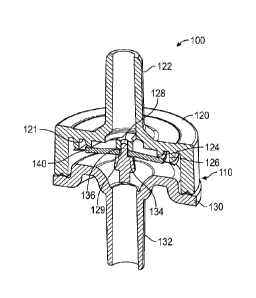
[0014] FIG. 1 depicts a schematic view of a typical assembled
infusion set.
[0015] FIG. 2 is a perspective exploded view of an example check
valve, according to
some aspects of the disclosure.
[0016] FIG. 3 is a cross-sectional perspective view of the check
valve of FIG. 2,
according to some aspects of the disclosure.
[0017] FIG. 4 is a partial cross-sectional perspective view of
the check valve of FIG. 2 in
a pre-assembled state, according to some aspects of the disclosure.
10018] FIG. 5 is a front view of the check valve of FIG. 4,
according to some aspects of
the disclosure.
[0019] FIG. 6 is a partial cross-sectional perspective view of
the check valve of FIG. 2 in
an assembled state, according to some aspects of the disclosure.
[0020] FIG. 7 is a front view of the check valve of FIG. 6,
according to some aspects of
the disclosure.
[0021] FIG. 8 is a perspective view of a check valve seal,
according to some aspects of
the disclosure.
[0022] FIG. 9 is a front view of the check valve seal of FIG. 8,
according to some aspects
of the disclosure.
[0023] FIG. 10 is a schematic view of the check valve of FIG. 7
in an open flow state,
according to some aspects of the disclosure.
- 4 -
CA 03177684 2022- 11- 2
WO 2021/226259
PCT/US2021/030924
DETAILED DESCRIPTION
[0024] The detailed description set forth below describes
various configurations of the
subject technology and is not intended to represent the only configurations in
which the
subject technology may be practiced. The detailed description includes
specific details for
the purpose of providing a thorough understanding of the subject technology.
Accordingly,
dimensions are provided in regard to certain aspects as non-limiting examples.
However, it
will be apparent to those skilled in the art that the subject technology may
be practiced
without these specific details. In some instances, well-known structures and
components are
shown in block diagram form in order to avoid obscuring the concepts of the
subject
technology.
100251 It is to be understood that the present disclosure
includes examples of the subject
technology and does not limit the scope of the appended claims. Various
aspects of the
subject technology will now be disclosed according to particular but non-
limiting examples.
Various embodiments described in the present disclosure may be carried out in
different
ways and variations, and in accordance with a desired application or
implementation.
[0026] As shown in FIG. 1, a typical infusion set 30 may include
a drip chamber 40, a
check valve 50, a roller clamp 60 and Y-junctions 70, all connected together
by tubing 20. A
typical infusion set 30 can include additional infusion components (e.g.,
pinch clamps,
filters) and can be formed of any combination of components and the tubing 20.
[0027] Check valve 50 is typically formed from flexible (e.g.,
elastomeric) seals mounted
within a fluid flow housing. Typically, the flexible seal is mounted such that
the seal
engages a seal bead in the housing in the sealed position and flexes away from
the seal bead
in an open flow position. However, if a particulate in the fluid becomes
caught between the
seal and the seal bead, a gap will remain between the seal and the seal bead
when the check
valve 50 returns to the sealed position. This gap allows for leakage (e.g.,
low flow leakage)
of fluid when the check valve 50 is supposed to be fully sealed to prevent any
fluid flow.
[0028] According to aspects of the disclosure, a check valve
assembly is provided with a
seal having dual sealing rings and a housing having dual seal beads. The outer
seal prevents
- 5 -
CA 03177684 2022- 11- 2
WO 2021/226259
PCT/US2021/030924
particulate (e.g., grit) from reaching the inner seal, thus allowing the inner
seal to fully close
and to seal off fluid flow.
[0029] FIGS. 2-10 illustrate a check valve assembly shown as
check valve 100, according
to some aspects of the disclosure. The check valve 100 includes a housing 110
having an
inlet body 120, an outlet body 130 and a seal 140.
[0030] The inlet body 120 has a fluid inlet 122 configured to
connect with a fluid source
(e.g., IV bag, infusion pump, needleless syringe) via an IV tube (e.g., tubing
20). The inlet
body 120 includes a first seal bead 124 and a second seal bead 126, each
disposed on an
inner surface 121 of the inlet body 120. The first and second seal beads 124,
126 may be
configured as cylindrical ribs or teeth, for example. As shown in FIG. 3, the
first seal bead
124 is a circular rib disposed around a central channel 128 in the inlet body
120. The central
channel 128 has an end surface 129.
[0031] As shown in FIG. 5, the first seal bead 124 has an inner
diameter Di and a height
Hi. The second seal bead 126 is a circular rib disposed concentrically around
the first seal
bead 124, the second seal bead 126 having an inner diameter D2 and a height
H2. Here, the
height FL is greater than the height Hi so that the second seal bead 126
extends further away
from the inner surface 121 than does the first seal bead 124. In some aspects
of the
disclosure, an end surface 123 of the first seal bead 124 and/or an end
surface 125 of the
second seal bead 126 is angled such that only a point portion of the end
surface 123, 125
engages with the seal 140 when the check valve 100 is in a fully sealed (e.g.,
closed)
position.
[0032] The outlet body 130 has a fluid outlet 132 configured to
connect with a
downstream fluid component (e.g., roller clamp 60). The outlet body 130
includes a stem
134 having a centering post 136 and a shoulder 138, the centering post 136 is
configured to
be received by the central channel 128 of the inlet body 120.
[0033] The seal 140 includes an inner ring 142 and an outer ring
144. The inner ring 142
has a thickness Ti and the outer ring 144 has a thickness T2, where thickness
Ti is greater
than thickness T, (see FIG. 9). The inner ring 142 has a diameter Dsi and the
outer ring 144
- 6 -
CA 03177684 2022- 11- 2
WO 2021/226259
PCT/US2021/030924
has a diameter D52, Where diameter 1352 is greater than diameter Dsi. The
diameter Dsi of the
inner ring 142 of the seal 140 is greater than the inner diameter Di of the
first seal bead 124,
and the diameter DS2 of the outer ring 144 of the seal 140 is greater than the
outer diameter
D2 of the second seal bead 126. The seal 140 also includes a central hole 146
that mounts on
the centering post 136 of the outlet body 130 and a portion of the inner ring
142 that rests on
the shoulder 138 of the outlet body 130. The seal 140 may be formed of any
flexible
material (e.g., silicone), where the inner ring 142 is somewhat flexible and
the outer ring 144
is thinner and more flexible. For example, the outer ring may be as thin as
mold flash.
[0034] To assemble the check valve 100, the seal 140 is coupled
to/mounted on the
centering post 136 of the outlet body 130 via the central hole 146 of the seal
140, where the
inner ring 142 rests on the shoulder 138 of the outlet body 130. As shown in
FIGS. 4 and 5,
the inlet body 120 is coupled to/mounted on the outlet body 130, which causes
the outer ring
144 to be engaged and loaded by the second seal bead 126. As shown in FIGS. 6
and 7, the
inlet body 120 and the outlet body 130 may then be sealed together (e.g.,
ultrasonic welding),
which causes the inner ring 142 to be sandwiched and/or secured between the
shoulder 138
of the outlet body 130 and the end surface 129 of the central channel 128, and
further causes
the inner ring 142 to be engaged and loaded by the first seal bead 124. Thus,
during
assembly of the check valve 100, the outer ring 144 is loaded first and the
inner ring 142 is
loaded second. In some aspects of the disclosure, the inner ring 142 and the
outer ring 144
have different preload forces_
10035] As shown in FIG. 10, the check valve 100 is in an open or
fluid flow mode when
fluid enters through the fluid inlet 122 with sufficient force to force the
inner ring 142 and
the outer ring 144 away from the first seal bead 124 and the second seal bead
126,
respectively. Thus, the inner ring 142 is flexed away from the first seal bead
124 and the
outer ring 144 is flexed away from the second seal bead 126 in this open fluid
flow position
of the check valve assembly 100. The fluid flows through the interior volume
112 of the
housing 110 and out the fluid outlet 132 of the outlet body 130. When the
fluid pressure
decreases or ceases (e.g., fluid flow slows or stops), the check valve 100
moves to a closed
position.
- 7 -
CA 03177684 2022- 11- 2
WO 2021/226259
PCT/US2021/030924
[0036] As the check valve 100 closes, the outer ring 144 closes
first by flexing back to its
starting position to engage the second seal bead 126. This occurs because the
outer ring 144
is thinner and more flexible than the inner ring 142, thus causing the outer
ring 144 to flex
faster and/or through a great range of motion than the inner ring 142. By
closing first, the
outer ring 144 creates an initial seal that prevents particulate or grit from
reaching the inner
ring 142. Thus, the outer ring 144 is engaged with the second seal bead 126
and the inner
ring 142 is still flexed away from the first seal bead 124 in this partially
sealed position of the
check valve assembly 100.
[0037] After the outer ring 144 closes, the inner ring 142 then
closes by flexing back to its
starting position to engage the first seal bead 124. Thus, the inner ring 142
is able to close
completely because of the absence of particulate or grit caused by the earlier
sealing of the
outer ring 144. Thus, the inner ring 142 is engaged with the first seal bead
124 and the outer
ring 144 is engaged with the second seal bead 126 in this fully sealed
position of the check
valve assembly 100.
[0038] For the seal 140, the inner ring 142 is the primary seal
and the outer ring 144 is the
secondary seal. Characteristics of the inner ring 142 primary seal determines
the cracking
pressure of the check valve 100 (e.g., the amount of fluid pressure required
to open or crack
the seal 140), such as the flexibility of the inner ring 142, for example. In
some aspects of
the disclosure, the cracking pressure is determined by the inner ring 142
because the outer
ring 144 secondary seal is very thin and has little resistance to the fluid
pressure. In some
aspects of the disclosure, the cracking pressure is determined by the inner
ring 142 because
the inner ring 142 primary seal is sealed against the first seal bead 124,
which prevents any
fluid from reaching the outer ring 144 secondary seal. Once the cracking
pressure is reached
in the check valve 100, both the inner ring 142 primary seal and the outer
ring 144 secondary
seal move away from the first seal bead 124 and the second seal bead 126
(e.g., open up) to
allow fluid to flow past the seal 140.
[0039] The operation of the check valve 100 may be varied by
modifying different
elements. For example, increasing/decreasing either or both the thickness Ti
of the inner ring
142 and the thickness T2 of the outer ring 144, increasing/decreasing either
or both the
- 8 -
CA 03177684 2022- 11- 2
WO 2021/226259
PCT/US2021/030924
diameter Di of the inner ring 142 and the diameter D2 of the outer ring 144,
increasing/decreasing either or both the height Hi of the first seal bead 124
and the height H2
of the second seal bead 126, and using various materials to change the
stiffness or flexibility
of either or both the inner ring 142 and the outer ring 144 may change the
cracking pressure
and/or flow characteristics of the check valve 100.
[0040] It is understood that any specific order or hierarchy of
blocks in the methods of
processes disclosed is an illustration of example approaches. Based upon
design or
implementation preferences, it is understood that the specific order or
hierarchy of blocks in
the processes may be rearranged, or that all illustrated blocks be performed.
In some
implementations, any of the blocks may be performed simultaneously.
[0041] The present disclosure is provided to enable any person
skilled in the art to
practice the various aspects described herein. The disclosure provides various
examples of
the subject technology, and the subject technology is not limited to these
examples. Various
modifications to these aspects will be readily apparent to those skilled in
the art, and the
generic principles defined herein may be applied to other aspects.
[0042] A reference to an element in the singular is not intended
to mean "one and only
one" unless specifically so stated, but rather "one or more." Unless
specifically stated
otherwise, the term "some" refers to one or more. Pronouns in the masculine
(e.g., his)
include the feminine and neuter gender (e.g., her and its) and vice versa.
Headings and
subheadings, if any, are used for convenience only and do not limit the
invention.
[0043] The word "exemplary" is used herein to mean "serving as
an example or
illustration.- Any aspect or design described herein as "exemplary- is not
necessarily to be
construed as preferred or advantageous over other aspects or designs. In one
aspect, various
alternative configurations and operations described herein may be considered
to be at least
equivalent.
[0044] As used herein, the phrase "at least one of' preceding a
series of items, with the
term "or" to separate any of the items, modifies the list as a whole, rather
than each item of
the list. The phrase "at least one of' does not require selection of at least
one item; rather,
- 9 -
CA 03177684 2022- 11- 2
WO 2021/226259
PCT/US2021/030924
the phrase allows a meaning that includes at least one of any one of the
items, and/or at least
one of any combination of the items, and/or at least one of each of the items.
By way of
example, the phrase "at least one of A, B, or C" may refer to: only A, only B,
or only C; or
any combination of A, B, and C.
[0045]
A phrase such as an "aspect" does not imply that such aspect is
essential to the
subject technology or that such aspect applies to all configurations of the
subject technology.
A disclosure relating to an aspect may apply to all configurations, or one or
more
configurations. An aspect may provide one or more examples. A phrase such as
an aspect
may refer to one or more aspects and vice versa. A phrase such as an
"embodiment" does
not imply that such embodiment is essential to the subject technology or that
such
embodiment applies to all configurations of the subject technology. A
disclosure relating to
an embodiment may apply to all embodiments, or one or more embodiments. An
embodiment may provide one or more examples. A phrase such an embodiment may
refer to
one or more embodiments and vice versa. A phrase such as a "configuration"
does not imply
that such configuration is essential to the subject technology or that such
configuration
applies to all configurations of the subject technology.
A disclosure relating to a
configuration may apply to all configurations, or one or more configurations.
A
configuration may provide one or more examples. A phrase such a configuration
may refer
to one or more configurations and vice versa.
[0046]
In one aspect, unless otherwise stated, all measurements, values,
ratings, positions,
magnitudes, sizes, and other specifications that are set forth in this
specification, including in
the claims that follow, are approximate, not exact. In one aspect, they are
intended to have a
reasonable range that is consistent with the functions to which they relate
and with what is
customary in the art to which they pertain.
[0047]
It is understood that the specific order or hierarchy of steps,
operations or
processes disclosed is an illustration of exemplary approaches. Based upon
design
preferences, it is understood that the specific order or hierarchy of steps,
operations or
processes may be rearranged. Some of the steps, operations or processes may be
performed
simultaneously. Some or all of the steps, operations, or processes may be
performed
- 10 -
CA 03177684 2022- 11- 2
automatically, without the intervention of a user. The accompanying method
claims, if any,
present elements of the various steps, operations or processes in a sample
order, and are not
meant to be limited to the specific order or hierarchy presented.
100481 All structural and functional equivalents to the elements of the
various aspects
described throughout this disclosure that are known or later come to be known
to those of
ordinary skill in the art are expressly incorporated herein by reference and
are intended to be
encompassed by the claims. Moreover, nothing disclosed herein is intended to
be dedicated
to the public regardless of whether such disclosure is explicitly recited in
the claims.
Furthermore, to the extent that the term "include," "have," or the like is
used, such term is
intended to be inclusive in a manner similar to the term "comprise" as
"comprise" is
interpreted when employed as a transitional word in a claim.
100491 The Title, Background, Summary, Brief Description of the Drawings and
Abstract
of the disclosure are hereby incorporated into the disclosure and are provided
as illustrative
examples of the disclosure, not as restrictive descriptions. It is submitted
with the
understanding that they will not be used to limit the scope or meaning of the
claims. In
addition, in the Detailed Description, it can be seen that the description
provides illustrative
examples and the various features are grouped together in various embodiments
for the
purpose of streamlining the disclosure. This method of disclosure is not to be
interpreted as
reflecting an intention that the claimed subject matter requires more features
than are
expressly recited in each claim. Rather, as the following claims reflect,
inventive subject
matter lies in less than all features of a single disclosed configuration or
operation. The
following claims are hereby incorporated into the Detailed Description, with
each claim
standing on its own as a separately claimed subject matter.
100501 The claims are not intended to be limited to the aspects described
herein, but are to
be accorded the full scope consistent with the language claims and to
encompass all legal
equivalents.
- 11 -
Date Recue/Date Received 2023-01-03