Note : Les descriptions sont présentées dans la langue officielle dans laquelle elles ont été soumises.
CA 03191725 2023-02-13
WO 2022/036317 PCT/US2021/046130
- 1 -
SHEAR RESISTANT GEOMEMBRANE
USING MECHANICAL ENGAGEMENT
Technical Field
The present invention relates to geomembranes having high shear resistance for
use in stabilizing piles or mounds of deposited aggregations of materials.
More
particularly, the present invention relates to shear resistant geomembranes
that
mechanically engage to overlying fabric liners for use in stabilizing layered
deposit
aggregations in layers, piles, or built-up mounds of granular particulate and
solids
materials, which layers are susceptible to plane shear failure arising from
lack of force
loading on the aggregation or shear load applied on the geomembranes,
especially on
sloped surfaces.
In this application, the following terms will be understood to have the
indicated
definitions:
waste sites - refers to earthen berms and to sites where waste is deposited,
such as
landfills, phosphogypsum stacks, environmentally impacted land, leach pads,
mining
spoils and environmental closures or material stockpiles that require a
closure or cover
system;
synthetic grass - -refers to a composite of at least one geotextile (woven or
nonwoven) tufted or knitted with one or more synthetic yarns or strands that
has the
appearance of grass;
geomembrane - -refers to a structured or textured polymeric material, such as
high-density polyethylene, very low-density polyethylene, linear low-density
CA 03191725 2023-02-13
WO 2022/036317 PCT/US2021/046130
- 2 -
polyethylene, polyvinyl chloride, provided as an impermeable sheet for liner
purposes in
the waste site and land site industry.
Background of the Invention
Large area aggregations of particulate and solids materials collected together
as a
mass of distinct parts are found in a wide range of structural applications.
These
applications include landfill and waste storage sites, manufacturing products
storage
laydown areas and by-product waste storage and holding fields, stockpiles,
power plant
disposal fields, reinforced foundations for roadways, retaining wall
structures, and the
like. Such applications typically involve the depositing of particulate and
solids materials
often in sloped landsite collections or aggregations but may be substantially
planar layers
of such materials as well. For example, landfills and waste sites typically
form sloped
collections of the particulate and solids materials deposited in layers,
piles, and mounds
for long term storage and containment. Planar structures such as for roadways
and
backfill for retaining wall structures typically have stacked layers of
particulate and solids
materials, which layers may be of differing materials characteristics such as
materials or
particulate type, grade, and layer dimensions.
Each of such aggregations are susceptible to planar failures arising from
shear
loading. Planar failure may cause catastrophic slope failure and avalanche
conditions in
which the material within the aggregation suddenly releases and moves under
loading.
The loading may arise from the mass of the materials in the aggregation
becoming
released from engagement or external forces, particularly, for example,
hydraulic shear
forces arising from water flow across the aggregation or across a covering
closure
CA 03191725 2023-02-13
WO 2022/036317 PCT/US2021/046130
- 3 -
system, such as caused by rain storms or by vertical acceleration and
deceleration forces,
or combinations of such internal and external loading forces.
Landfills and waste sites, for example, typically remain open for a number of
years for receiving waste materials, mining spoils or power plant wastes and
ash, landfill
trash and municipal solids and liquids wastes. Such waste sites typically have
steep
slopes rising from a toe or base to an upper elevated apex or peak as the
additional
deposits of waste materials are made over time. The elevation may typically
reach
several hundred feet above the toe with deposits over time of fill materials.
While steep
slopes allow geometrically increased storage volume, steep slopes experience
significantly high shear forces. These forces occur in response to the fill
materials loaded
in within a vertical portion of the area allocated for the landfill and also
arise from
precipitation and water flow such as from rain fall on the waste site that
generates high
volumes of water flowing downwardly to the toe. Steep slopes often experience
large
and rapid run-off Upon reaching an appropriate capacity for the particular
site, the site is
closed to receiving additional waste materials. Closure involves overlaying a
water
impermeable ground cover such as a geomembrane and a synthetic drainage system
over
the aggregation land site. The ground cover restricts water inflow into the
collected
particulate and solids materials to prevent contamination of below-grade water
tables
while the synthetic drainage system provides for water flow off of the cover
system.
Ground cover design and installation needs to consider cover stability for the
long-term
post-closure covering of the site.
Closure systems for landfills use geomembranes and synthetic drainage systems
covered by soil (typically 18 inches to 24 inches) for developing a final
grass growth on
CA 03191725 2023-02-13
WO 2022/036317 PCT/US2021/046130
- 4 -
the upper soil surface. The weight or mass of the soil develops friction to
resist shear
loading and site slope failures. The synthetic drainage is composite layered
sheet having
a core geonet mesh sheet with spaced-openings and sandwiched by a fabric
overlay that
restricts soil from filing the openings and a fabric underlay that sits on the
upper surface
of the aggregation site to be closed. Ambient and environmental water such as
from rain
or snow percolates through the soil and flows off the covered site by the
synthetic
drainage system. However, in recent years, landfills have been covered with
lightweight
(lighter than the soil mass) geosynthetics such as synthetic grass of tufted
fabric backing.
While there are benefits to synthetic grass ground covers, the weight of such
covers is
insufficient for developing friction to avoid sliding on steep slopes (for
example, up to
1:1 gradients) in high shear loading that occurs particularly during rail
storms. Also,
planar applications such as road ways and retaining wall backfill aggregations
include
stacked layers of granular materials, particulates, and soil materials. These
structures
provide foundations for roadway and secure retaining walls.
To increase resistance to shear loading and thus resistance to slope failure,
installations typically include spaced geomembrane sheets between adjacent
layers of fill
materials. The interposed geomembrane provides a frictional engagement with
the
adjacent layers of fill materials, whereby the aggregation becomes interlinked
and
stabilized against planar failure.
While geomembranes providing frictional resistance to planar failure and
increased aggregation stability, there are drawbacks. The frictional
resistance may be
insufficient to retain the fill materials under loading, typically extreme
loading, such as
from heavy rainfall events and flooding that in combination with internal
loading creates
CA 03191725 2023-02-13
WO 2022/036317 PCT/US2021/046130
- 5 -
high shear forces on the aggregation. For example, light weight synthetic
grass or tufted
geosynthetic sheets overlaid on steep sloped ground surfaces lack sufficient
mass or
weight to develop frictional surface-to-surface engagement that resists the
shear forces
causing sloped aggregation failure and movement.
Accordingly, there is a need in the art for an improved geomembrane having
increased shear resistance for use in covering closure of materials
aggregation
applications using confining pressures that otherwise surface exposed layered
materials
cannot achieve. It is to such that the present invention is directed.
Summary of the Invention
The present invention meets the need in the art by providing an improved
geomembrane for use in resisting shear loading in materials aggregation
applications and
in reducing stabilization failures of materials aggregation applications. The
improved
geomembrane comprises an elongated polymeric impermeable sheet having opposing
surfaces with a plurality of spaced-apart first projections extending from a
first surface,
which first projections mechanically engage, puncture, or pierce a respective
geotextile
sheet with the geomembrane in contact with adjacent fill materials within the
aggregation, whereby the aggregation has increased resistant to shear failure
of the
aggregation of fill materials.
In another aspect, the present invention meets the need in the art by
providing a
ground cover system for a covering closure of a land site, comprising an
elongated
polymeric impermeable sheet having opposing first and second surfaces, for
overlying a
ground surface to be closed, with a plurality of spaced-apart first
projections extending
from the first surface. The first projections each tapering to a pointed apex
at a distal
CA 03191725 2023-02-13
WO 2022/036317 PCT/US2021/046130
- 6 -
extent. A
covering for overlying the first surface of the elongated polymeric
impermeable sheet, which first projections for mechanically engaging,
puncturing, or
piercing the covering. Upon covering installation, the aggregation has
increased
resistance to shear failure of the aggregation of fill materials for reducing
stabilization
failures of materials in aggregation land sites.
In another aspect, the present invention provides an aggregation cover system
for
a covering closure, comprising a liner sheet having opposing first and second
surfaces,
for overlying an aggregation surface to be closed and a plurality of spaced-
apart spikes
extending from the first surface, each said first projections tapering to a
respective
pointed apex at a distal extent. A tufted geosynthetic of a backing sheet
tufted with yarns
to define a plurality of spaced-apart tufts of synthetic grass blades
extending from the
backing sheet as a covering for overlying the first surface of the liner
sheet, whereby said
spikes for mechanically engaging the backing sheet to resist movement of the
tufted
geosynthetic during shear loading while the tufted geosynthetic frictionally
engages the
aggregation surface. The aggregation has increased resistance to shear failure
of the
aggregation of fill materials for reducing stabilization failures of materials
in aggregation
land sites.
In the geomembrane as recited above, the first projections are spaced apart to
have a first density.
In the geomembrane as recited above, an alternate embodiment further comprises
a plurality of spaced-apart second projections extending from a second
opposing surface.
In the geomembrane as recited above, in which the second projections are
spaced
apart to have a second density.
CA 03191725 2023-02-13
WO 2022/036317 PCT/US2021/046130
- 7 -
The geomembrane as recited above, wherein the first projections and the second
projections extend from the respective surface to an extent from about 10
mills to about
100 mills relative to the respective surface, and preferably the extent is
about 40 mils.
The geomembrane as recited above, wherein the first projections are spikes,
spines, or pointed pins, knobs, posts, extending members, or projections with
distal
pointed tips, angled tipped members, for mechanical puncture or piercing
engagement
with an adjacent overlying sheet material.
The geomembrane as recited above, wherein the second projections are spikes,
spines, or pointed pins, knobs, posts, extending members, or projections with
distal
pointed tips, angled tipped members, for further mechanical puncture or
piercing
engagement with exposed surface layer of the collected particulate and solids
materials.
The geomembrane as recited above, wherein an extent of the respective first
projections is of a first length and the extent of the respective second
projections is of a
second length, the first length different from the second length.
The geomembrane as recited above, wherein at least the first projections have
an
axis oriented on a perpendicular relative to the surface of the geomembrane.
The geomembrane as recited above, wherein at least the first projections have
an
axis oriented at an oblique angle relative to a perpendicular to the surface.
The geomembrane as recited above, wherein the oblique angle of the axis of the
first projections is from about 1 degree to about 45 degrees, preferably from
about 5
degrees to about 20 degrees, and more preferably from about 10 degrees to
about 15
degrees.
CA 03191725 2023-02-13
WO 2022/036317 PCT/US2021/046130
- 8 -
The geomembrane as recited above, wherein the geomembrane has an interface
shear strength to resist shear load.
Objects, advantages, and features of the improved geomembrane and cover
system will become apparent upon a reading of the detailed description in
conjunction
with the drawings illustrating various embodiments of the improved
geomembrane.
Brief Description of the Drawings
Fig. 1A illustrates in perspective view a first embodiment of a geomembrane in
accordance with the present invention.
Fig. 1B illustrates in perspective view a second embodiment of a geomembrane
in
accordance with the present invention.
Fig. 1C illustrates in perspective view a third embodiment of a geomembrane in
accordance with the present invention.
Fig. 2 illustrates in cross-sectional view the geomembrane illustrated in Fig.
1A.
Fig. 3 illustrates in detailed cross-sectional view the geomembrane
illustrated in
Fig. 1B.
Fig. 4 illustrates in schematic view a manufacturing effect to define a
gripping
apex for the spikes formed for use with the geomembrane illustrated in Figs.
1A ¨ 1C.
Fig. 5 illustrates in perspective view an alternate embodiment of the
geomembrane illustrated in Fig. 1A with a textured surface.
Fig. 6 illustrates in exploded cross-sectional view an aggregation application
using the geomembrane in mechanical engagement with a fabric overlay for
aggregation
stabilization and resisting shear force failure, in accordance with the
present invention.
CA 03191725 2023-02-13
WO 2022/036317 PCT/US2021/046130
- 9 -
Fig. 7 illustrates in cross-sectional view a sloped surface of an aggregation
application on a land site using a synthetic drainage assembly overlaid by a
mass material
soil for holding frictional engagement between the synthetic drainage assembly
and the
overlaid surface.
Fig. 7A illustrates in perspective view a detailed portion of the synthetic
drainage
assembly having a geocomposite textile /geonet mesh / textile structure.
Fig. 8 illustrates in exploded cross-sectional view an aggregation application
using the geomembrane of the present invention in mechanical and frictional
engagement
with an improved synthetic drainage of a geonet mesh for aggregation
stabilization and
resisting shear force failure, in accordance with the present invention.
Fig. 9 illustrates in exploded cross-sectional view an aggregation application
using the geomembrane of the present invention in mechanical and frictional
engagement
with a lightweight tufted geosynthetic for aggregation stabilization and
resisting shear
force failure, in accordance with the present invention.
Fig. 10 illustrates in exploded cross-sectional view an aggregation
application
using the geomembrane of the present invention in mechanical and frictional
engagement
with a lightweight tufted geosynthetic for aggregation stabilization and
resisting shear
force failure, in accordance with the present invention.
Detailed Discussion
With reference to the drawings, in which like parts have like identifiers,
Fig. 1A
illustrates in perspective view a geomembrane 20 in accordance with the
present
invention. The geomembrane 20 is a polymeric extruded elongated sheet having
CA 03191725 2023-02-13
WO 2022/036317 PCT/US2021/046130
- 10 -
opposing surfaces 22, 24 and generally having a length and width significantly
greater
than a thickness. A plurality of spaced-apart first projections or spikes 26
populate the
geomembrane extending from the first surface 22. As discussed below, the
projections
26 on the first surface mechanically engage respective geotextile sheets that
are adjacent
aggregation fill materials above (or below) the respective geotextile sheet,
whereby the
aggregation of fill materials has increased resistance to shear forces. For
example, the
geomembrane 20 may install as an impermeable liner for a landfill, an overlay
component of a landfill site closure system, a stabilizing foundational layer
in a roadway
subsurface, or a stabilizing layer in a backfill of a retaining wall
structure.
Fig. 1B illustrates in perspective view a second embodiment of a geomembrane
20b in accordance with the present invention. The geomembrane 20b differs from
the
geomembrane 20 with a plurality of spaced-apart second projections 28
extending from
the second opposing surface 24. The projections 26, 28 may be tapered spikes
each with
a distal pointed apex 29, such as extending tips, spinesõ pins, knobs, posts,
extending
members, projections with distal pointed tips, angled tipped members, or other
shaped
extending members that may engage, puncture, or pierce a portion of the fill
materials, a
geotextile sheet, soil, waste, or fill material at a land site. The
projections 26 may be
different from the projections 28.
Fig. 1C illustrates in perspective view a third embodiment of a geomembrane
20c
in accordance with the present invention. The geomembrane 20c differs from the
geomembrane 20 with a texturing of the second opposing surface 24. Thus, the
geomembrane 20C uses the projections 26 extending from the first side while
the
CA 03191725 2023-02-13
WO 2022/036317 PCT/US2021/046130
- 11 -
opposing second side may be textured, or alternatively, smooth, without
projections
extending from the second side.
With reference to Fig. 2, the projections 26in the illustrated embodiment are
conical elongated members or spikes that each taper conically from the surface
22to an
apex 29. The apex 29 preferably defines a pointed tip for piercingly engaging
a surface,
such as a back surface of a geotextile sheet as discussed below. Fig. 2 is
exaggerated in
scale for illustration purposes because the projections 26 extend from about
10 mills to
about 150 mills, and preferably about 40 ¨ 120 mills, and more preferably
about 100
mills. The spikes 26 define relatively small extending textured presence on
the surface of
the geomembrane. The base of the spike 26 has a diameter of about 25 mills to
about 100
mills, preferably about 40 mills to about 85 mills, more preferably about 60
mills. The
projections 28 illustrated in alternate embodiment in Fig. lb are similar
conical elongated
members or spikes extending from the bottom surface 24. The spacing (or
density of
distribution) of the first projections 26 may selectively be the same as or
different than
the spacing (or density of distribution) of the second projections 28. The
spacing of the
projections 26, 28 may range from about 1 projection per square foot to about
60
projections per square foot, more preferably from about 25 projections per
square foot to
about 50 projections per square foot, and more preferably about 36 projections
per square
foot (providing in such embodiment a 2 inch spacing (machine direction and
cross
direction) of adjacent projections 26, 28). However, a preferred embodiment
may have
as few as one to five spikes per square foot. The particular spacing (and thus
the number
of projections per square inch) is derived by considering the interface
resistance required
between the geomembrane 20 and material to be mechanically engaged, such as a
CA 03191725 2023-02-13
WO 2022/036317 PCT/US2021/046130
- 12 -
geotextile or synthetic grass or turf sheet discussed below to maintain the
tufted
geotextile free from slippage relative to the geomembrane and especially
during high
hydraulic sheer forces from water flow during precipitation and water flooding
conditions, and particularly proximate lower portions of steep slopes of
covered land
surfaces. Generally, fewer, but taller projections 26, 28 are preferred for
extending into
and mechanically engaging, piercing, or penetrating a synthetic drainage layer
such as in
a ground covering embodiment that includes an overlay of a synthetic grass or
tufted
geosynthetic .
The geomembrane 20 is preferably made of very low density polyethylene, linear
low density polyethylene (LLDPE), high density polyethylene (HDPE), or
polyvinyl
chloride.
The illustrated embodiments provide an interface resistance to slippage of
aggregations of particulate and solids materials such as slippage occurring
between layers
of the aggregation or slippage of sloped surfaces. In a covering application
discussed
below in Fig. 9, the plurality of first projections 26 engage grippingly a
synthetic
drainage layer overlaid by a tufted geotextile sheet (such as a lightweight
geocomposite
drainage and synthetic turf) and restrict lateral movement of the fill
materials relative to
the geomembrane 20. In the embodiment of Fig. 1B, the plurality of second
projections
28 further engage grippingly a surface (such as a ground surface or fill
material). In the
illustrated embodiment, a density of 1 to 36 projections 26 per square foot
provides
mechanical engagement interface resistance sufficient to hold the overlaid
tufted
geotextile from movement and allow frictional forces to restrict lateral
movement of the
fill material relative to the geomembrane 20 especially on steep slopes.
Alternate
CA 03191725 2023-02-13
WO 2022/036317 PCT/US2021/046130
- 13 -
embodiments may have a lower, or greater, density of projections 26 , for
example, as
low as one (1) projection per square foot. The present invention provides the
projections
26 that mechanically engage for securing the covering, such as the tufted
geosynthetic
from movement and cooperatively allow the mass of the covering to develop
resisting
frictional forces to the shear forces that cause movement and slope failure of
the
aggregation which otherwise such lightweight synthetic covers develop
insufficient
frictional engagements.
Oriented Spiked Geomembrane
Fig. 3 illustrates in enlarged cross-sectional view the geomembrane 20 with
the
spaced-apart first projections or spikes 26 extending from the first surface
22. The
projections 26 in the illustrated embodiment orient to have a tilt angle in
opposition to a
machine direction of the sheet. The extrusion process deforms the projections
26 before
cooling of the extruded geomembrane 20. The tilt angle of the projections 26
forms
during calendaring of the extruded sheet between opposing calendar rollers
that define
the spikes or projections that cooperatively develop shear resistance in use
in a covering
system. The process applies a pulling force on the extruded sheet slightly
faster than the
infeed rate of the sheet from the extruder die of the extrusion into a gap
between a pair of
opposing calendar rollers. This slightly deforms the projections 26 from a
perpendicular
axis to have a tilted axis of less than 90 degrees relative to a perpendicular
to the surface
22. The tilted projection in the illustrative embodiment thereby has a leaning
edge in the
projection such that the projection functions as a tooth, for example, to grab
a portion of a
bottom surface of a geotextile sheet, or a portion of a synthetic drainage
layer for
mechanical high strength engagement between the geomembrane and the engaged
layer
CA 03191725 2023-02-13
WO 2022/036317 PCT/US2021/046130
- 14 -
(a geotextile sheet or synthetic geocomposite drainage layer or synthetic
turf), and thus,
provide stabilization of the fill material in a materials aggregation
application. The
second embodiment of the geomembrane 20b similarly forms the tilted
projections 28
with respective tips 29.
As illustrated in Fig. 3, the projection 26 is a leaning spike having a cross-
sectional oblique angle a, with a leaning edge angled relative to a
perpendicular to the
surface. The oriented spikes thereby have a tilt or angle a from perpendicular
relative to
the surface. As illustrated schematically in Fig. 4, the tilt angle a is
between about 1
degree to about 45 degrees, preferably about 5 degrees to about 20 degrees,
and more
preferably about 10 degrees to about 15 degrees. The apex 29 thereby defines
an angled
pointed tip for engaging a fabric or geotextile. The plurality of spikes 26
cooperatively
distributes the loading on the fabric or geotextile to resist slippage
relative to the
geomembrane 20.
Fig. 5 illustrates an alternate embodiment of a geomembrane sheet 20a in which
at
least one surface 66 defines a texture generally 68, such as protruding ridges
and recessed
valleys among the projections 28. One or both surfaces 22, 24 may have the
texture 68.
Aggregation Applications
As noted above, the geomembrane 20 may be used for providing resistance to
high shear forces that may arise in materials aggregation applications, such
as in
mounded or layered infill aggregation applications including landfill and
waste site
operations including as a site liner or as a component of a covering system
for closure of
CA 03191725 2023-02-13
WO 2022/036317 PCT/US2021/046130
- 15 -
a landfill. In
such application involving sloped land for closing coverage, the
geomembrane 20 is preferably oriented with the pointed apex 29 of the spikes
26 facing
uphill in opposition to a force inducing slippage downwardly along sloped land
but may
be oriented facing downhill or transverse on sloped surfaces. In other
applications, the
geomembrane 20 may be installed as a stabilizing layer in a layered backfill
for retaining
walls or as a foundational layer in a roadway application. Fig. 6 illustrates
in exploded
detailed cross-sectional view a materials aggregation application 70 with one
of the
geomembranes 20 mechanically engaged to a fabric or geotextile sheet 72 for
resisting
shear forces and increase stabilization of the fill material 74 in the
materials aggregation
70. Also, as illustrated, the geomembrane 20 may mechanically engage a lower
geotextile sheet 76. A lower portion of the materials aggregation site may
alternately
include a transitory layer 78 such as a smaller particulate material and a
liner 80
(preferably impermeable to water flow) overlying a ground surface 82.
The geotextile sheet 72 comprises a woven or non-woven textile. In the
illustrated embodiment, the geotextile sheet 72 is non-woven but may be woven
with
warp and waft yarns. The geotextile sheet 72 has a weight basis or mass of
between
about 3 ounces per square yard to about 16 ounces per square yard, more
preferably about
6 ounces per square yard to about 9 ounces per square yard, and preferably of
about 6 to
8 ounces per square yard.
Fig. 7 illustrates in cross-sectional view a sloped portion of a surface of an
aggregation application 90 such as a mounded waste material landfill on a land
site
covered with a prior art closure system generally 91. The landfill site is
closed with the
covering closure system 91 using a synthetic drainage assembly 92 overlaid by
a mass
CA 03191725 2023-02-13
WO 2022/036317 PCT/US2021/046130
- 16 -
material 94 for holding frictional engagement between the synthetic drainage
assembly
and the overlaid surface. Fig. 7A illustrates in perspective view a detailed
portion of the
synthetic drainage assembly 92 having a synthetic mesh grid 95 with an
attached
overlying permeable fabric layer 96 and an underlying nonpermeable layer 98.
The
.. synthetic mesh grid 95 defines a plurality of space-apart openings 100
therethrough. The
mass material 94 typically comprises a layer of dirt, typically 18 inches to
24 inches,
overlaid on the synthetic drainage assembly 92. The dirt as the mass material
94
develops friction between the synthetic drainage layer and the aggregation,
which resists
slope failure. The mass material 94 loads the synthetic drainage assembly 92
on the
surface and seeks to resist sliding of the site covering system. Ambient or
environmental
water such as rail fall percolates through the dirt layer and along the mesh
grid 94 to
drainage. Despite the loading of the mass material 94, slippage nevertheless
occurs.
Fig. 8 illustrates in exploded cross-sectional view an aggregation application
110
using the geomembrane 20 in mechanical and frictional engagement with a land
site
covering system of a mass material 94 overlying a synthetic drainage system
112 for
aggregation stabilization and resisting shear force failure, in accordance
with the present
invention. In this illustrated embodiment, the mass material 94 comprises a
layer of soil
or dirt but less volume than required in the site application illustrated in
Fig. 6. The
synthetic drainage system 112 comprises the synthetic mesh grid 95 and fabric
layer 96
for preventing dirt from filing the openings 100 in the mesh grid. The apex
defining
spikes 20 (illustrated in cut-away detailed view) inter-engage mechanically
with the
synthetic drainage layer 95 and the covering soil 94 provides mass for
frictional
CA 03191725 2023-02-13
WO 2022/036317 PCT/US2021/046130
- 17 -
engagement of the geomembrane 20 to the surface of the aggregated materials
placed in
the landsite.
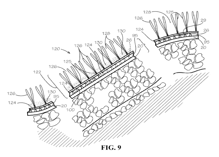
Fig. 9 illustrates in exploded cross-sectional view (partially cut-away) an
aggregation application 120 using the geomembrane 20 in mechanical engagement
with
the mesh grid 95 as the synthetic drainage system overlaid by a synthetic
grass or tufted
geosynthetic 122 for aggregation stabilization and resisting shear force
failure, in
accordance with the present invention. The tufted geosynthetic 122 comprises a
fabric
backing 124 tufted with elongated yarns to define a plurality of spaced-apart
tufts 125 of
synthetic grass blades 126. The tufts 125 define interstices 128 therebetween.
The spikes
26 of the geomembrane 20 mechanically engage grippingly the geomesh grid 95
overlaid
by the tufted geosynthetic 122 as a covering system. Alternatively, as
illustrated, the
tufted geosynthetic 122 may be weighted with an overfill 130 of particulates,
sand,
combination sand and cement material, or the like. The overfill 130 shades the
tufts 125
from UV degradation and provides a mass for further frictional contact between
the
geomembrane and the slip-prone covering of the aggregation of the land site.
The backing sheet 124 may be a woven or non-woven textile, and may comprise
one or a plurality of separate sheets tufted together. The backing sheet 124
may have
weight basis or mass of between about 6 ounces per square yard to about 24
ounces per
square yard. The tufting yarns interweave through the backing to define spaced-
apart
rows of the tufts 125 that extend from the geosynthetic 20 as the grass-like
blades 126.
The tufts 125 tuft on spacing in a range from about 1/4 inch to 1 inch,
preferably 1/2 inch.
The blades 126 extend from the backing sheet 124 about 1/2 inch to about 4
inches, and
more preferably from about 1 inch to about 1 and 1/2 inches. The adjacent
blades 126
CA 03191725 2023-02-13
WO 2022/036317 PCT/US2021/046130
- 18 -
define the interstices 128. The interstices 128 receive the distributed
granular infill 130
selectively to a fill plane (preferably less than and no more than a greatest
extent defined
by about a distal extent of the blades 126). The backing sheet 124 forms of a
polymer
material that resists exposure to sunlight that generates heat rise in the
geosynthetic 20
and that resists ultraviolet (UV) radiation in the sunlight, which degrades
the backing
sheet and the tufted blades. The polymer yarns further should not become
brittle when
subjected to low temperatures. The color selection of the yarns for the
backing sheet 124
are preferably black and/or gray yarns. The color selection for the tufting
yarns are green
or brown, to simulate tufts 126 of grasses. The tufts may be tufted in
combinations for
.. closer simulation of the area to be covered, for example using a respective
proportion of a
first, second, or more, color yarns. Further, the polymeric material for the
yarns that are
woven to form the backing sheet or the polymers spun bond for a non-woven
backing
sheet, include UV resistant additives such as HALS and carbon black. The
polymers are
selected to provide high shear strength resistance for the geotextile 20. The
backing sheet
has strong tensile strength, in a range of about 1,000 pounds per foot to
about 4,000
pounds per foot.
The cover system may gainfully use the granular infill 130 received within the
interstices 128 between the tufts 125. The infill 130 is a granular material
cooperating
with the extending blades 126 of the tufts 24 to shadow the backing sheet 22
and further
enhances the friction developed with the tufted geosynthetic covering. The
infill 130 fills
onto the backing sheet 124 and within the interstices 128 therefrom preferably
to about a
second extent that is generally less than the fill plane of the geosynthetic.
The infill 130
cooperates with the blades 126 to shadow the backing sheet 124 from UV
exposure and
CA 03191725 2023-02-13
WO 2022/036317 PCT/US2021/046130
- 19 -
degradation. The infill 38 may be a sand material, and further particularly
may comprise
a fire retardant additive or product independent of a sand carrier mixture,
such as a non-
halogenated magnesium hydroxide powder, silicates including potassium
silicate,
calcium silicate, and sodium silicate, or other in situ fire suppression or
resistant material.
Fig. 10 illustrates an alternate embodiment 130 for level, or substantially
level
aggregation or ground surfaces. The spikes 26 of the geomembrane 20 make
mechanical,
piercing engagement with the backing 124 of the synthetic grass tufted
geosynthetic 122
for aggregation stabilization and resisting shear force failure, in accordance
with the
present invention. As illustrated, the tufted geosynthetic 122 may
alternatively include
the additional mass of the particulate infill 130 that further provides UV
shading for
reduced degradation of the tufted geosynthetic 122 and enhances development of
friction
of the lightweight tufted geosynthetic grass 122. The spikes 26 of the
geomembrane 20
mechanically engage grippingly the backing 124 of the overlaid tufted
geosynthetic 122
as a covering system. The mechanical engagement resists movement of the
geosynthetic
under shear loading whereby the mass develops frictional engagement to resist
aggregation slippage or movement. With a level or slightly sloped surface, the
ambient
water passes through the infill and the backing 124 to travel on the upper
surface of the
geomembrane in interstices between the upper surface and the geomembrane. The
spikes
26 retain the tufted geosynthetic 122 in covering relation and while thereby
stabilized
from movement the tufted geosynthetic develops frictional engagement for
resisting shear
forces. In an alternate application for level or slightly sloped surfaces, the
infill 130
further shades the tufted geosynthetic 122 from UV degradation but also
enhance the
CA 03191725 2023-02-13
WO 2022/036317 PCT/US2021/046130
- 20 -
frictional engagement that is cooperatively enhanced by the spikes 26 to
resist shear
loading.
The foregoing discloses an improved geomembrane for use in resisting shear
loading in materials aggregation applications and in reducing stabilization
failures of
materials aggregation applications, comprising an elongated polymeric
impermeable
sheet having opposing surfaces with a plurality of spaced-apart first
projections extending
from a first surface, which projections for mechanically engaging a synthetic
drainage
overlaid by a respective geotextile sheet and in contact with adjacent fill
materials within
the aggregation, whereby the aggregation has increased resistance to shear
failure of the
aggregation of fill materials. While the invention has been described with
particular
reference to various embodiments, variations and modifications can be made
without
departing from the spirit and scope of the invention recited in the appended
claims.