Note : Les descriptions sont présentées dans la langue officielle dans laquelle elles ont été soumises.
~ WO94/~001 215 7 6 6 ~ PCT~094/00059
AN OPTICAL ARRANGEME~T FOR FLOW CYTOMETERS.
The present invention relates to an optical arrangement for flow
cytometers.
A flow cytometer is an instrument for measurement of the
fluorescence and light scattering of individual biological cells
and other types of microscopical particles. In the flow cytometer
the cellæ are carried by a laminar flow of water through the
focus of a high intensity light source. The cells are typically
stained with a fluorescent dye which binds specifically to one
particular cell constituent. Each cell passing through the focus
will thus emit a short pulse of fluorescence and scattered light.
The intensity of the fluorescence will be proportional to the
15 cellular content of fluorescent dye and thereby with the cellular
content of the stained constituent. The intensity of the
scattered light and its angular distribution is a complex
function of the size, shape, structure and chemical composition
of the cell. By measuring with separate detectors the light
20 scattering at small and large scattering angles, respectively,
it is thus possible to distinguish cells on the basis of size,
shape, and structure.
For some purposes the cells may be stained by two or three
25 different dyes which bind to dilferent cellular constituents and
fluoresce at different wavelengths. The corresponding spectral
components of the fluorescence can be separated by dichroic
mirrors and band filters and measured by separate detectors.
~ence, each cell may generate several signals; typically two
30 light scattering signals - low and large angle scatterlng - and
two or three fluorescence signals. This technology is well known
and has been published in many articles, e.g. in "Flow cytometry
and sorting" (Melamed, ~.R.; Lindmo, T; ~endelsohn, M.L., Eds.),
Wiley-Liss, New York 1990.
The cellular content of the constltuent(s) to be measured may be
quite small, that is down to about 1-10-18 g/cell. The demands
WO94/~OOl PCT~094100059 ~
2157~65
on the sensltivity of the instrument are correspondingly high.
In order to achieve such sensitivity the e~citation light has to
be concentrated intc a very small and correspondingly intense
focus. Furthermore, the optics which collects the fluorescence
5 and scattered light must have the highest possible numerical
aperture. It is essential also that any light from other sources
than the cells, e.g. the background due to fluorescence and light
scattering from optics and other components in the optical path,
is as low as possible.
There are two ma~or types of flow cytometers: a) Instruments
employing a laser as the source of e~citation light, and b)
instruments using a high pressure arc lamp with xenon or mercury.
The laser-based instruments have the advantage that the
15 e~citation light can be focused into a very small and corre-
spondingly intense focus. Furthermore, the beam of egcitation
light is near parallel, which simplifies the distinction of light
scattered to different angles. Arc lamp-based instruments have
the advantage that the spectrum of the light source contains all
20 wavelengths from ~V through the visible spectrum. Hence, by means
of appropriate filters the proper wavelength for excitation of
any fluorescent dye can be selected, thus making this type of
instruments more versatile.
25 All laser-based flow cytometers have essentially the same optical
configuration, namely so that the vertical sample stream cuts
through the focus of a horizontal laser beam and so that this
focus is intersected at a 90 degree angle by the optical axis of
the optics which collects the fluorescence and the light
30 scattered to large angles, i.e. around 90. Behind the light
collecting optics fluorescence and light scattering are separated
by a dichroic mirror and directed onto separate light detectors.
The fluorescence may be further split into different spectral
components by additional dichroic mirrors and measured by
35 separate detectors.
~ WO94/22001 21~7 6 65 PCT~094/00059
The light of the focused laser beam is near parallel, that is
falling within a light cone of about 2 or less. Hence, the light
scattering at low scatterlng angles is measured through an other
lens with lts optical axis coincident with the laæer beam. The
5 laser beam is prevented from entering the lens by a field stop
situated in front of the lens.
Some lsser-based flow cytometers employ two lasers emitting at
different wavelengths and focused to separate foci, so that the
o cells are egcited sequentially with two different wavelengths.
Thus, it becomes possible to measure two different dyes which
cannot be e~cited by the same wavelength or which interfere in
ways which are not compatible with the measurement. Such "two
focus e~citation" has many interesting biological applications.
All arc lamp-based flow cytometers employ epi-illumination, which
is to say that the optics which concentrate the light in the
excitation focus, also collects the fluorescence. In order to
achieve the highest possible e~citation lntensity as well as
20 optimal fluorescence collection efficiency, this optics should
have the highest possible numerical aperture (NA). ~ence, an oil
immersion microscope lens, having NA _ 1,3, is used for this
purpose.
25 The large field an~le of the illumination field of such a lens
makes it impossible to distinguish the light scattering at small
and large scattering angles by the same type of optical con-
figuraion as that usede in the laser-based instruments. The
Norwegian patents no. 145.176 and 156.917, as well as ~S-paten$s
30 no. 4.408.877 and 4.915.501 disclose how light scattering can be
measured in the epi-illumination type of optical configuration
used in arc lamp-based instruments. By means of a central field
stop close to the back focal plane of this lens, a dark field is
created which allows measurement of light scattering at both
35 small and large scattering angles through a second microscope
lens situated opposite to the first and with its aperture within
the dark field produced by the field stop in the first lens.
WO94/~001 ~ 6 6 ~ PCT~094/00059
However, this configuration has certain shortcomings. Thus, it
allows the light scattering at large angles to be measured only
within a very small aperture, i.e. NA ~ 0,04. This small aperture
limits the sensitivity of the measurement of this parameter.
5 Furthermore, with this configuration the "large angle" range has
a lower limit which does not e~ceed about 20.
Another disadvantage of the epi-illumination configuration of
current arc lamp-based flow cytometers is that it does not allow
o excitation in two separate foci of different wavelength, thus,
limiting to some e2tent the range of applications of such
instruments. The epi-illumination also implies that the optics
which collects the fluorescence, i.e. said microscope objective,
is exposed to very high intensities of e~citation light. Even
15 with microscope ob~ectives of the very highest quality this is
causing some fluorescence from the elements of the ob~ective
which adds to the background on which the cell fluorescence is
detected, and thereby to a reduction of the signal to noise
ratio, which is equivalent to a reduction of the sensitlvity.
The present invention is a novel optical configuratlon which
eliminates some of the above mentioned limitatlons of current
designs of arc lamp-based flow cytometers. Thus, the present
invention facilitates large angle llght scatterlng measurement
25 at considerably hlgher scattering angles and with a much higher
numerical aperture than was feasible with the previous con-
flguration. Hence, the light scattering sensitlvlty is con-
siderably increased relative to current designs. It also produces
less background light in the fluorescence light path, and allows
30 "two focus excitation".
More specifically, the present invention provldes an optical
arrangement for flow cytometer, wherein intense light is focused
by a microscope objective or similar lens having a numerical
35 aperture NAi onto a stream of cells carried by a laminar flow of
water through the focal plane of sald ob~ective; and wherein
another microscope lens is situated opposite to said objective,
~ W094/~1 21~ 7 ~ 6 5 PCT~094/00059
and wlth its optical a~is and ob~ect plane coinciding with those
of said ob~ective, and with a numerical aperture, NAo, which is
significantly larger than that of said ob~ective wherein said
ob~ective contains a circular central field stop in, or close to,
5 its secondary focal plane, said field stop having a diameter
corresponding to a numerical aperture, NAdf, which is slightly
larger than NAi, while it is much less than NAo, so that the
illumination field of said ob~ective falls entirely within said
field stop, and hence so that the image of said stream of cells
10 created by said objective contains only fluorescence and
scattered light from said stream of cells; wherein said
fluorescence and scattered light from said stream of cells are
separated by a dichroic mirror on bssis of their different
wavelength, so that said fluorescence and scattered light give
15 rise to separate images of said stream of cells in separate image
planes of said ob~ective; and wherein a telescope, situated
immediately oehind said image plane creates an image of said
field stop in a plane, where is situated two concentric mirrors,
of different diameter, which separate light scattered from said
20 stream of cells to different scattering angles and direct said
scattered light of different scattering angles onto separate
light detectors.
According to a further feature of the invention, said stream of
25 cells coincides with said ob~ect plane of said objectives, and
said stream of cells is illuminated through said ob~ective in one
or two ad~acent foci of different wavelength emitted by two
separate light sources.
30 According to another feature of the invention first and second
slits may cover the image of each of said ad~acent foci from said
light sources in said ob~ect plane, so that fluorescence measured
behind said first slit originates from only one of said foci
whereas fluorescence measured behind said second slit originates
~5 only from the other of said foci.
W094/~00l 21~7 6 ~5 PCT~094100059 ~
According to get another feature of the invention, said mirrors
in said image plane of said telescope are flat, polished end
planes that are cut at an angle of 45 of two concentric tubes
having their common axis coinsiding with the optical a~is of said
5 telescope.
The invention is now to be de~cribed with reference to a
preferred, non-limitative embodiment of the invention.
10 Figure 1 shows the optical arrangement for flow cytometers,
according to the invention.
Figure 2 shows more detailed a telescope formed image, according
to the invention.
Figure 3 shows a concentric mirror embodiment, according to the
invention.
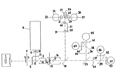
The invention, shown schematically in Figures 1, 2 and 3, is a
20 device which contains a light source 1 which, through a lens 2,
illuminates an egcitation slit 3, which is situated in the image
plane 4 of a microscope ob~ective or similar lens 5 which
concentrates the excitation light from said light source 1 in an
excitation focus 6 in the ob~ect plane 7 of said ob~ective 5. An
25 interference band filter 8 is situated in the light path behind
said objective 5 in order to isolate the appropriat~ wavelength
of excitation.
The device can also include a secondary light source 9 which,
30 through a lens 10, illuminates an excitation slit 11. An image
of this slit 11 is formed by said lens 5 in said image plane 7
via a dichroic mirror 12. An interference filter 1~ isolates a
band of excitation wavelength, preferably not overlapping that
of said band filter 8. Said egcitation slits 3 and 11 are
~5 situated so that their images in said ob~ect plane 7 do not
overlap, but are closely ad~acent on each side of the optical
axis 14 of said lens 5.
W094/~00l ~1 5 7 6 6 5 PCT~094/00059
The sample stream, containing cells or other microscopical
particles to be measured, is conducted by the measuring chamber
15 in said ob~ect plane 7 through said optical a~is 14 of said
lens 5.
Another microscope ob~ective 16, preferably of the oil immersion
type with a numerical aperture of approximately NA - 1,3, is
situated opposite said lens 5 so that the two ob~ectives 5 and
16 have their respective optical axis 14 and respective object
10 plane 7 coinciding.
Inside said ob~ective 16 is a central, circular field stop 17,
with its center in said optical a~is 14 and in a plane which is
close to the back focal plane of said objective 16. Said field
15 stop 17 covers the central part of the aperture of said ob~ective
16, thus stopping light falling within a solid angle corre-
sponding to a numerical aperture, NAdf, which is ~ust slightly
larger than the numerical aperture, NAi, of said lens 5. Hence,
e~citation light focused onto said ob~ect plane 7 by said lens
20 5 is not transmitted by said ob~ectlve 16. Consequently, the
light collected by said ob~ective 16 will contain only
fluorescence and scattered light from said sample stream through
said measuring chamber 15. Behind said ob~ective 16 is situated
a dichroic mirror 18 with a characteristic wavelength so that
25 said scattered light is reflected to form an image of said sample
stream in an image plane 19 of said ob~ective 16, whereas the
fluorescence is transmitted to form a corresponding image in the
image plane 20 of said ob~ective 16.
30 Behind said image plane 19 is a telescope 21 which forms an
image, as shown in figure 2, of the plane containing said field
stop 17 in a plane 23. Outside the dark field 22, which is the
image of said field stop 17, is light scattered from cells in
said sample stream. It will be understood that light falling at
35 a given distance, r, from the center of said image in said plane
23 is emitted with scattering angles exceeding a certain limit,
~1 (Eq. 1) and below an upper limit, ~2 (Eq.2).
PCT~094/00059
~1 ~ arcsin[(r/rO)(NAdf/n)] - arcsin(NAi/n) Eq.(1)
~2 ~ arcsin[(NAO + NAi)/n] Eq.(2)
5 where n is the refractive inde~ of the sample stream, usually
water, and rO the radius of said image 22 of said field stop 17,
as determined by the magnification of said telescope 21.
It can be seen that the lowest scattering angle which can be
10 detected in said image plane 23, that is, at the periphery of the
image 22 of the field stop 17 where r ~ rO, is given by:
~1(min) _ arcsin(NAdf/n - arcsin(NAi/n) Eq.(~)
15 The largest scattering angle that can be detected, i.e. at the
outer periphery of the image (Fig. 2) in said lmage plane 23,
where:
r r(ma~) ~ rO(NAO/NAdf) Eq.(4)
ls given by:
~1(max) ~ arcsin(NAO/n) - arcsin(NA1/n) Eq.(5)
25 The theory of light scattering from microscopical particles as
well as experimental data on this phenomenon shows that the
intensity of the scattered light falls off very rapidly with
lncreasing scattering angle over the entire range from 0 to about
60. Hence, a light scattering signal collected over a certain
30 range of scattering angles will be strongly dominated by
scattering from angles close to the lower limit of this range.
Thus, a light scattering signal collected ~ust outside the
periphery of said image 22 of said field stop 17, to a good
approximation will represent low scattering angles, that is
35 angles ~ust above ~1(min); whereas light collected close to the
outer periphery contains only light from large scattering angles,
that is, upwards from about ~1(ma~).
~ WO94/~001 2 ~ 5 7 6 6 ~ PCT~094/00059
A suitable value for NAi is 0,60, whereas NAdf ~ 0,62 and NAo ~
1,~. Accordlng to E~s. 3 and 5, these values give: ~1(min) -
0,97 and ~1(ma~) ~ 51.
5 The two light scattering components representing low and large
scattering angles, respectively, are dlrected onto separate light
detectors by means of two concentric mirrors 24 and 25 (Fig. 3)
formed by the plane, polished front surfaces of two cylindrical
tubes which are cut at 45 to their a~is and which are coa~ial
10 with the optical a~is of æaid telescope 21~ Said mirrors 24 and
25 face in opposite directions, as shown in Fig. 3. The inner
tube 26 has an inner diameter equal to rO, while the inner
diameter of the outer tube 27 is a little less than rma~. Said
mirrors 24 and 25 both have their center in said image plane 23.
15 The outer tube 27 has an opening 28 in that side which is facing
said mirror 24, so that the light reflected by said mirror 24 can
pass through said opening 28 and through a lens 29 to reach said
~detector 30. The light reflected from said mirror 25 is directed
through a lens 31 onto a detector 32.
Between said dichroic mirror 18 and said image plane 20 is
another dichroic mirror 33 which directs certain wavelengths of
fluorescence, usually shorter wavelengths, to form an image from
said ob~ective 16 in the plane 34, whereas fluorescence of other
25 wavelengths, usually longer, is transmitted to form an image in
said plane 20. Thus, the device e~hibits three separate image
planes 19, 20 and 24 for said ob~ective 16, wherein the same
image is formed in three different regions of wavelength. In each
OI` said image planes 19, 20, and 24 is situated a rectangular
30 slit, the size of which can be varied so as to match the size of
t~:e image of the illuminated part of said stream of cells in said
f'ow chamber 1~ in order to eliminate light from other parts of
said ob~ect plane 7 and thereby suppress background light which
otherwise reduces the signal to noise ratio of the light
35 c~lection and thereby the sensitivity.
WO941~001 PCT~094/00059 ~
2~ ~7~g~
Dichroic mirrors 38 and 39 and optical band filters 40, 41, 42
and 43 are situated behind said slits 36 and 37 in order to
æeparate different spectral components of the fluorescence and
direct these spectral components onto separate detectors 44, 45,
s 46 and 47.
Said dichroic mirror 18 is chosen so as to separate the scattered
light, which is reflected, from the fluorescence which is
transmitted because of its longer wavelength. Said dichroic
10 mirror 33 separates the fluorescence into two different spectral
components, each of which is further separated by said dichroic
mirrors 38 and 39. Thus, the present device can measure four
different fluorescence components. This method of separating
different spectral components of fluorescence is well known from
the literature, e.g. "Flow cytometry and sorting", Melamed et al,
Wiley-Liss, New York 1990. It is trivial to increase the number
of fluorescence spectral components further b~ the addition of
more dichroic mirrors and band filters.
20 An important feature of the invention is that it facilitates so-
called "two focus excitation". Light from two separate light
sources 1 and 9 is passed through different band pass filters 8
and 13 which transmit two different spectral bands of excitation
light. The optical axis of these two spectral bands are somewhat
25 shifted relative to each other so that said ob~ective 5 forms two
ad~acent excitation foci in said ob~ect plane 7. Hence, said
cells will pass sequentially through said two excitation foci.
Said slits 36 and 37 are situated so that they cover the image
of each of said two excitation foci. Hence, the fluorescence
30 emitted from each of said excitation foci is separated from each
other and can thus be measured by separate detectors.
In the case that such "two focus excitation" is employed, one of
the fluorescence detectors, for example 44 or 47 may be used to
35 measure the scattered light from cells excited in that of said
excitation foci which has the largest excitation wavelength. The
invention thus facilitates measurement of scattered light at two
~ WO g4/22001 ~ ~ ~
~ ~ 1 5 7 ~ 6 5 PCT~094/00059
different wavelengths and may thereby pro~ide further information
about the cells that are being measured.
~0