Sélection de la langue

Search

Sommaire du brevet 2166907 

Énoncé de désistement de responsabilité concernant l'information provenant de tiers

Une partie des informations de ce site Web a été fournie par des sources externes. Le gouvernement du Canada n'assume aucune responsabilité concernant la précision, l'actualité ou la fiabilité des informations fournies par les sources externes. Les utilisateurs qui désirent employer cette information devraient consulter directement la source des informations. Le contenu fourni par les sources externes n'est pas assujetti aux exigences sur les langues officielles, la protection des renseignements personnels et l'accessibilité.

Disponibilité de l'Abrégé et des Revendications

L'apparition de différences dans le texte et l'image des Revendications et de l'Abrégé dépend du moment auquel le document est publié. Les textes des Revendications et de l'Abrégé sont affichés :

  • lorsque la demande peut être examinée par le public;
  • lorsque le brevet est émis (délivrance).
(12) Brevet: (11) CA 2166907
(54) Titre français: ENSEMBLE A SIFFLET DEVIATEUR POUR TUBE CHEMISE
(54) Titre anglais: WHIPSTOCK ASSEMBLY FOR A SLEEVED CASING
Statut: Réputé périmé
Données bibliographiques
(51) Classification internationale des brevets (CIB):
  • E21B 7/08 (2006.01)
  • E21B 7/06 (2006.01)
  • E21B 17/00 (2006.01)
  • E21B 34/14 (2006.01)
  • E21B 43/14 (2006.01)
(72) Inventeurs :
  • COON, ROBERT JOE (Etats-Unis d'Amérique)
(73) Titulaires :
  • BAKER HUGHES INCORPORATED (Etats-Unis d'Amérique)
(71) Demandeurs :
  • BAKER HUGHES INCORPORATED (Etats-Unis d'Amérique)
(74) Agent: SIM & MCBURNEY
(74) Co-agent:
(45) Délivré: 2006-04-25
(22) Date de dépôt: 1996-01-10
(41) Mise à la disponibilité du public: 1996-07-13
Requête d'examen: 2002-12-30
Licence disponible: S.O.
(25) Langue des documents déposés: Anglais

Traité de coopération en matière de brevets (PCT): Non

(30) Données de priorité de la demande:
Numéro de la demande Pays / territoire Date
08/371,868 Etats-Unis d'Amérique 1995-01-12

Abrégés

Abrégé français

Tubage muni d'une gaine de ripage obturable. Un sifflet déviateur peut être inséré dans le tubage et peut être supporté hors du tubage à un emplacement prédéterminé de sorte qu'il est orienté vers une fenêtre ouverte dans le tubage lorsque la gaine de ripage est sélectivement déplacée vers le haut. En présentant une fenêtre ouverte pour le sifflet déviateur orienté vers la fenêtre, il est possible d'abaisser un foret à travers le tubage pour interagir avec le sifflet déviateur pour commencer immédiatement le forage du puits de forage dévié. Le foret creuse dans le ciment éventuellement présent et dans la formation. Un alésage est présenté dans le sifflet déviateur pour permettre la production des zones productrices sous le sifflet déviateur pendant qu'il est en place. En cas de nécessité, la gaine coulissante peut être ensuite fermée pour isoler le puits de forage dévié qui a été foré avec le sifflet déviateur à travers la fenêtre ouverte.


Abrégé anglais

A casing is provided with a sealable shifting sleeve. A whipstock is insertable into the casing and may be supported off of the casing in a predetermined location so that it is oriented toward an open window in the casing when the shifting sleeve is selectively moved upwardly. By presenting an open window for the whipstock oriented toward the window, a drillbit may be lowered through the casing to interact with the whipstock to immediately begin the drilling of the deviated wellbore. The drillbit cuts through any cement, if present, and into the formation. A bore is presented in the whipstock to allow production from pay zones below the whipstock while it is in place. Should it become necessary, the sliding sleeve may be subsequently closed to isolate the deviated wellbore which has been drilled with the whipstock through the open window.

Revendications

Note : Les revendications sont présentées dans la langue officielle dans laquelle elles ont été soumises.


CLAIMS

1. An apparatus for creating sidetrack in a wellbore extending from a
surface location, comprising:
a tubular housing insertable in the wellbore extending adjacent a point
where the sidetrack is to commence, said housing further comprising:
a cover selectively movable over an opening formed in said tubular
housing between a first position where said opening is covered and a second
position where said opening is exposed;
a whipstock supported by said housing, said whipstock having a
tapered guiding surface in alignment with said opening whereupon when said
cover
is selectively placed in said second position, a sidetrack can be drilled
through said
opening.
2. The apparatus of claim 1, wherein:
said cover is shiftable between said first and second positions from
the surface of the wellbore;
said opening is sealingly closed when said cover is in its said first
position.
3. The apparatus of claim 2, wherein said housing further comprises:
a shoulder; and
said whipstock comprises at least one collet movable past said shoul-
der in a first direction but engaging said shoulder in a reversed second
direction.
4. The apparatus of claim 3, wherein:
said collet is connected to a sleeve;


8


said whipstock further comprises at least one engagement dog retained
against radially outward movement by said sleeve until said collet moves said
sleeve to release said dog radially for engagement with said housing.
5. The apparatus of claim 4, further comprising:
an engagement groove on said housing; and
said engagement dog shaped to prevent movement of said whipstock
in said first direction when extended into said engagement groove.
6. The apparatus of claim 5, further comprising:
at least one locking dog on said whipstock and a matching locking
groove on said housing; and
said whipstock forcing said locking dog into said locking groove upon
application of force to said whipstock in said first direction after said
engagement
dog is supported by said engagement groove on said housing.
7. The apparatus of claim 6, wherein:
longitudinal support for said whipstock is transferred from said
engagement dog to said locking dog as a result of movement of said whipstock
in
said first direction after said engagement dog is in said engagement groove.
8. The apparatus of claim 7, further comprising:
an orientation groove in said housing;
at least one orientation lug in said whipstock;


9


whereupon when said lug is advanced into said orientation groove,
said tapered guiding surface on said whipstock is oriented toward said opening
in
said housing.
9. The apparatus of claim 8, wherein:
said orientation lug is outwardly biased; and
said orientation lug provides resistance to angular rotation of said
whipstock in said housing.
10. The apparatus of claim 9, further comprising:
a top section selectively movable with respect to a bottom section on
said whipstock;
said top section comprising a tapered surface for camming said
locking dog and said tapered guiding surface; and
said top section is keyed to said bottom section to prevent relative
rotation therebetween while allowing relative longitudinal movement to allow
said
tapered surface to cam said locking dogs.
11. The apparatus of claim 10, further comprising:
a temporary indexing mechanism acting on said top and bottom
sections to temporarily retain their relative positions in a first position
where said
locking dog is retracted and a second position where said tapered surface has
cammed said locking dog outwardly into said housing.
12. The apparatus of claim 11, wherein said indexing mechanism com-
prises:


a split ring in a groove in said top section and an upper and lower
opposed groove in said bottom section;
whereupon said split ring can selectively expand into one or the other
of said opposed grooves to selectively secure said top section to said bottom
section in two positions.
13. The apparatus of claim 1, further comprising:
a flowpath through said whipstock to allow production therethrough
with said whipstock in place.
14. The apparatus of claim 12, further comprising:
a flowpath through said whipstock to allow production therethrough
with said whipstock in place.
15. The apparatus of claim 13, further comprising:
an internal groove in said flowpath to facilitate engagement of said
whipstock by a fishing or retrieving tool for removal to the surface.

Description

Note : Les descriptions sont présentées dans la langue officielle dans laquelle elles ont été soumises.


5
TITLE: WHIPSTOCK ASSEMBLY FOR A SLEEVED CASING
INVENTOR: Robert Joe Coon
~FLD OF THE INVENTION
The field of this invention relates to whipstocks, particularly those that may
be supported by a casing, and more particularly those that can be used in
combina-
tion with a sleeve in the casing.
BACKGROUND OF THE INVENTION
Whipstocks have long been used to divert a milling tool to cut a new
opening through a casing. Typically in these installations, a packer is set in
the
casing which has a lug or some other guide mechanism to orient the whipstock.
The plug or packer is set in the casing and then the whipstock is secured to
the
packer in the appropriate orientation for the new deviated path to be milled
and
ultimately drilled. A milling tool is then used to cut through the casing.
Having
cut through the casing, the milling tool is removed to the surface and
drilling with
the appropriate bit commences.
Various designs of whipstocks and mounting systems therefor are illustrated
in U.S. Patents 2,506,799; 5,154,231; 3,397,746; 5,335,737; 5,341,873; and
5,115,872. --
U.S. Patents 5,156,220; 5,090,481; 4,991,654; and 4,880,059 illustrate the
use of sliding sleeves which can be selectively opened to exposed perforations
in
a casing, which can then permit flow into the casing. The Brandel patent
4,991,654 illustrates the use of disintegratable plugs in the openings. U.S.
Patents
4,397,360 and 4,807,704 illustrate the use of whipstocks to create lateral
wellbores
from the main wellbore.
1


It should be noted that some casings, particularly in deviated wellbores, may
not be cemented. Casing packers mounted externally to a section or sections of
casing can be used to isolate the casing from the wellbore.
The drawback of the current designs is that a separate mill must be em-
ployed to cut through the casing, which must then be retracted to the surface
so
that a drillbit can be mounted to allow the drilling to continue into the
formation.
The apparatus of the present invention seeks to eliminate the milling step by
providing a casing with a sleeve shiftable between an open and closed position
to
selectively open a window in the casing. The window may be closed during the
cementing operation and may be subsequently opened for forming the deviated
wellbore off of the whipstock. Should it be desired, the sleeve can, anytime
after
the drilling of the deviated wellbore and production therefrom, be fully
closed. The
whipstocks that can be employed with this system can be mounted from the
casing
directly and can also feature a bore therethrough to allow production from pay
zones below the whipstock.
SiIMMARY OF THE INVENTION
A casing is provided with a sealable shifting sleeve. A whipstock is insert-
able into the casing and may be supported off of the casing in a predetermined
location so that it is oriented toward an open window in the casing when the
shifting sleeve is selectively moved upwardly. By presenting an open window
for
the whipstock oriented toward the window, a drillbit may be lowered through
the
casing to interact with the whipstock to immediately begin the drilling of the
deviated wellbore. The drillbit cuts through any cement, if present, and into
the
formation. A bore is presented in the whipstock to allow production from pay
zones below the whipstock while it is in place. Should it become necessary,
the
2


CA 02166907 2005-06-23
sliding sleeve may be subsequently closed to isolate the
deviated wellbore which has been drilled with the
whipstock through the open window.
Accordingly, in one aspect of the present invention
there is provided an apparatus for creating sidetrack in
a wellbore extending from a surface location,
comprising:
a tubular housing insertable in the wellbore
extending adjacent a point where the sidetrack is to
commence, said housing further comprising:
a cover selectively movable over an opening formed
in said tubular housing between a first position where
said opening is covered and a second position where said
opening is exposed;
a whipstock supported by said housing, said
whipstock having a tapered guiding surface in alignment
with said opening whereupon when said cover is
selectively placed in said second position, a sidetrack
can be drilled through said opening.
BRIEF DESCRIPTION OF THE DRAWINGS
An embodiment of the present invention will now be
described more fully with reference to the accompanying
drawings in which:
Figures lA-D illustrate the casing segment, showing
the window and the sliding sleeve.
Figures 2A-D illustrate the run-in position.
Figure 3 illustrates the lower end of the casing in
section showing the support for the whipstock in the
lift-up position.
Figures 4A-F illustrate the casing of Figures 1 and
2, with the sleeve in the open position and the
whipstock installed in a position ready for drilling.
3


CA 02166907 2005-06-23
DETAILED DESCRIPTION OF THE PREFERRED EMBODIMENT
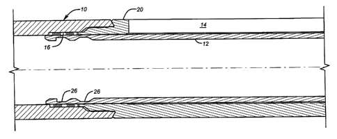
The body 10 is illustrated in Figures lA-D. A
sleeve 12 is shown in the closed position over a window
14. The window 14 is premade in the body 10 and can
extend as much as approximately 140° circumferentially.
It should be noted that the window 14 is not produced by
a milling tool but is provided in a specially formed
segment of the body 10.
In the preferred embodiment, chevron seals 16 and
18 are, respectively, present at the upper and lower
ends of window 14. Housing 20 retains the chevron seals
16 and 18 to the body 10. Sliding sleeve 12 has a
groove or grooves 26 near its upper end and a groove or
grooves 28 near its lower end for selective engagement
with shifting tool (not shown), of a type well-known in
the art. Use of the shifting tool (not shown) can move
the sleeve 12 from the position shown in Figure 1B,
wherein the window 14 is closed, to the position shown
in Figure 4B, where the window 14 is open. Those
skilled in the art will appreciate that different types
of seals other than a stack of opposed chevron seals can
be used as the sealing assembly 16 or 18 without
departing from the spirit of the invention.
3a


~~66~0
The whipstock 30 is shown in Figures 4A-F in the set
position. Whipstock 30 has a central bore 32 which
extends to a taper 34 at the upper end 36. Also located
in bore 32 is a groove 38, which is useful in attaching
the whipstock 30 to a running tool so that it can be
positioned in the position shown in Figure 3 from the
surface. Groove 38 may also be used for fishing
operations to assist in removal of a stuck whipstock 30
by merely pulling up. In normal operations, whipstock 30
is removed by pulling upon groove 38. Ring 33 can be
used to facilitate removal of lower segment 41 with upper
segment 39. The whipstock 30 has an upper segment 39 and
a lower segment 41. Lug 67 maintains upper segment 39 in
a specific orientation to lower segment 41 by keyway (not
shown) so that segments 39 and 41 can translate but not
rotate with respect to each other.
Attached to the lower end 40 of whipstock 30 is a
locating apparatus 42. The locating apparatus 42 is
shown in the set position in Figure 4E. In the set
position, the collet 44 has a surface 46 which is shown
hooked on mating surface 48 on the locating apparatus 42.
However, during the run-in position shown in Figures 2A-
D, surface 50 of collet 44 becomes juxtaposed adjacent to
surface 52 of mandrel 54 to clear surface 90 (see Figure
4F). Therefore, during the run-in-position, sleeve 56,
which has an upper end 58, interferes with dog 60,
holding it inwardly against the opposing force of biasing
spring 62. At the same time during run-in, dog 64 rides
on surface 66 of the whipstock 30. Whipstock 30 has a
groove 68 in which sits a split ring 70, which in the
run-in position is juxtaposed against groove 73, with
groove 74 misaligned with groove 68. Ultimately, when
there is latching, as shown in Figure 4E, grooves 68 and
74 come into alignment to allow split ring 70 to expand
and secure the position of locking dog or dogs 64 into a
groove 76 on the body 10. The whipstock 30 has a tapered
surface 78 adjacent to surface 66 so that in the latching
operation, the locking dogs 64 are caromed outwardly along
4


~~_~~~a~
surface 78 into groove 76 to secure the engagement of the
whipstock 30 to the body 10 for longitudinal support (see
Figure 4E).
The whipstock 30 has a locating dog 84 which is
formed to engage a locating groove 82 for proper
alignment of the taper 34 with the window 14 in a manner
known in the art. Locating dogs 84 are outwardly biased
by springs 86 to secure and orient the whipstock 30
against rotational forces during the drilling operation
through the window 14. the locating dogs 84 can be
displaced radially inwardly until they come into
alignment with their appropriate grooves in the body 10,
at which point the springs 86 push the dogs 84 outwardly
into their mating grooves. Since the dogs 84 are mounted
to the locating apparatus 42 in a manner that they cannot
rotate with respect to the locating apparatus 42, outward
movement of the locating dogs 84 into their respective
grooves effectively provides a rotational lock.
In running in the tool, the assembly of the
whipstock 30 with the locating apparatus 42 is run into
the body 10 with a suitable running tool. The assembly
is run in a first direction to below the position shown
in Figure 2A-D and then brought up in a second and
opposite direction (see Figure 3). Collet 44 is first
temporarily displaced into groove 88 so that it can clear
surface 90 as the assembly of the whipstock 30 and
locating apparatus 42 is run downwardly in said first
direction into body 10. Once the assembly of the
whipstock 30 and locating apparatus 42 are brought back
up in said second direction, the collets 44 have a
surface 92 which engages tapered surface 94 on body 10.
This results in movement of the collets 44 downwardly
into groove 96 to the position shown in Figure 4D.
Shifting the collets 44 downwardly into groove 96 moves
away the upper end 50 from the
5


engagement dogs 60, which allows them to move radially outwardly into groove
98 on body 10.
The dogs 60 have an extending segment 100 which, when latched into
groove 98, provides the initial longitudinal support for whipstock 30.
Thereafter,
when weight is set down on said upper segment 39, it moves in said first
direction
with respect to lower segment 41 as taper 78 cams locking dogs 64 and split
ring
70 enters groove 74. In short, the locating apparatus, in combination with the
body
10, provides for proper orientation of the whipstock 30 through the use of
locating
dogs 84 which fit into a special groove machined into the body 10.
Longitudinal
support for the whipstock 30 is provided by locking dogs 64. Engagement dogs
60 only temporarily support the whipstock 30 until the locking dogs 64 extend
into
the body 10. Rotational support for the whipstock 30 is provided by dogs 84
which go into mating depressions 82 in the body 10, thereby acting as keys
which
lock against torsional forces transmitted by the drilling operation through
the
window 14 to the whipstock 30.
Those skilled in the art will appreciate that by combining the feature of use
of the whipstock 30 along with a body that has a preformed window which can be
selectively covered by a sliding sleeve 12, time and money can be saved for
the
well operator. The reason for this is that in fewer trips into the bore the
complete
sidetrack can be accomplished. This is an improvement over past techniques
where
a milling tool is first used to make the opening in the casing. It is then
removed
and replaced by a drillbit to actually bore the deviated bore. In the present
inven-
tion, the window is opened with a shifting tool and the whipstock 30 is set
with a
running tool in one trip. Drilling a deviated wellbore then commences with a
drillbit in a second trip. A third trip of using the milling tool can be
eliminated.
6


~~.~~~v
A new manner of support of the whipstock has also been described which
allows proper support against rotation and longitudinal movement and proper
orientation, as well as a flow-through feature.
The foregoing disclosure and description of the invention are illustrative and
explanatory thereof, and various changes in the size, shape and materials, as
well
as in the details of the illustrated construction, may be made without
departing
from the spirit of the invention.
bakulpatcntsl325whip.app ss
7

Dessin représentatif
Une figure unique qui représente un dessin illustrant l'invention.
États administratifs

Pour une meilleure compréhension de l'état de la demande ou brevet qui figure sur cette page, la rubrique Mise en garde , et les descriptions de Brevet , États administratifs , Taxes périodiques et Historique des paiements devraient être consultées.

États administratifs

Titre Date
Date de délivrance prévu 2006-04-25
(22) Dépôt 1996-01-10
(41) Mise à la disponibilité du public 1996-07-13
Requête d'examen 2002-12-30
(45) Délivré 2006-04-25
Réputé périmé 2014-01-10

Historique d'abandonnement

Il n'y a pas d'historique d'abandonnement

Historique des paiements

Type de taxes Anniversaire Échéance Montant payé Date payée
Le dépôt d'une demande de brevet 0,00 $ 1996-01-10
Enregistrement de documents 0,00 $ 1996-04-04
Taxe de maintien en état - Demande - nouvelle loi 2 1998-01-20 100,00 $ 1998-01-02
Taxe de maintien en état - Demande - nouvelle loi 3 1999-01-11 100,00 $ 1999-01-05
Taxe de maintien en état - Demande - nouvelle loi 4 2000-01-10 100,00 $ 1999-12-23
Taxe de maintien en état - Demande - nouvelle loi 5 2001-01-10 150,00 $ 2000-12-28
Taxe de maintien en état - Demande - nouvelle loi 6 2002-01-10 150,00 $ 2001-12-28
Requête d'examen 400,00 $ 2002-12-30
Taxe de maintien en état - Demande - nouvelle loi 7 2003-01-10 150,00 $ 2002-12-30
Taxe de maintien en état - Demande - nouvelle loi 8 2004-01-12 150,00 $ 2003-12-30
Taxe de maintien en état - Demande - nouvelle loi 9 2005-01-10 200,00 $ 2004-12-23
Taxe de maintien en état - Demande - nouvelle loi 10 2006-01-10 250,00 $ 2006-01-09
Taxe finale 300,00 $ 2006-02-10
Taxe de maintien en état - brevet - nouvelle loi 11 2007-01-10 250,00 $ 2006-12-20
Expiré 2019 - Paiement rectificatif/L'article 78.6 150,00 $ 2007-01-26
Taxe de maintien en état - brevet - nouvelle loi 12 2008-01-10 250,00 $ 2007-12-18
Taxe de maintien en état - brevet - nouvelle loi 13 2009-01-12 250,00 $ 2008-12-17
Taxe de maintien en état - brevet - nouvelle loi 14 2010-01-11 250,00 $ 2009-12-18
Taxe de maintien en état - brevet - nouvelle loi 15 2011-01-10 450,00 $ 2010-12-17
Taxe de maintien en état - brevet - nouvelle loi 16 2012-01-10 450,00 $ 2011-12-19
Titulaires au dossier

Les titulaires actuels et antérieures au dossier sont affichés en ordre alphabétique.

Titulaires actuels au dossier
BAKER HUGHES INCORPORATED
Titulaires antérieures au dossier
COON, ROBERT JOE
Les propriétaires antérieurs qui ne figurent pas dans la liste des « Propriétaires au dossier » apparaîtront dans d'autres documents au dossier.
Documents

Pour visionner les fichiers sélectionnés, entrer le code reCAPTCHA :


Pour visualiser une image, cliquer sur un lien dans la colonne description du document. Pour télécharger l'image (les images), cliquer l'une ou plusieurs cases à cocher dans la première colonne et ensuite cliquer sur le bouton "Télécharger sélection en format PDF (archive Zip)" ou le bouton "Télécharger sélection (en un fichier PDF fusionné)".

Liste des documents de brevet publiés et non publiés sur la BDBC .

Si vous avez des difficultés à accéder au contenu, veuillez communiquer avec le Centre de services à la clientèle au 1-866-997-1936, ou envoyer un courriel au Centre de service à la clientèle de l'OPIC.


Description du
Document 
Date
(yyyy-mm-dd) 
Nombre de pages   Taille de l'image (Ko) 
Dessins représentatifs 1999-08-10 1 16
Page couverture 1996-01-10 1 18
Abrégé 1996-01-10 1 24
Description 1996-01-10 7 296
Revendications 1996-01-10 7 203
Dessins représentatifs 2004-11-09 1 13
Description 2005-06-23 8 321
Revendications 2005-06-23 4 116
Dessins 1996-01-10 15 254
Page couverture 2006-03-22 1 47
Correspondance 2006-02-10 1 52
Cession 1996-01-10 10 448
Poursuite-Amendment 2002-12-30 1 75
Poursuite-Amendment 2003-03-13 1 29
Poursuite-Amendment 2004-12-23 2 63
Poursuite-Amendment 2005-06-23 5 212
Poursuite-Amendment 2007-01-26 10 437
Correspondance 2007-03-05 1 14

Listes de séquence biologique

Sélectionner une soumission LSB et cliquer sur le bouton "Télécharger la LSB" pour télécharger le fichier.

Si vous avez des difficultés à accéder au contenu, veuillez communiquer avec le Centre de services à la clientèle au 1-866-997-1936, ou envoyer un courriel au Centre de service à la clientèle de l'OPIC.

Soyez avisé que les fichiers avec les extensions .pep et .seq qui ont été créés par l'OPIC comme fichier de travail peuvent être incomplets et ne doivent pas être considérés comme étant des communications officielles.

Aucun fichier LSB n'a été fourni.