Sélection de la langue

Search

Sommaire du brevet 2641252 

Énoncé de désistement de responsabilité concernant l'information provenant de tiers

Une partie des informations de ce site Web a été fournie par des sources externes. Le gouvernement du Canada n'assume aucune responsabilité concernant la précision, l'actualité ou la fiabilité des informations fournies par les sources externes. Les utilisateurs qui désirent employer cette information devraient consulter directement la source des informations. Le contenu fourni par les sources externes n'est pas assujetti aux exigences sur les langues officielles, la protection des renseignements personnels et l'accessibilité.

Disponibilité de l'Abrégé et des Revendications

L'apparition de différences dans le texte et l'image des Revendications et de l'Abrégé dépend du moment auquel le document est publié. Les textes des Revendications et de l'Abrégé sont affichés :

  • lorsque la demande peut être examinée par le public;
  • lorsque le brevet est émis (délivrance).
(12) Brevet: (11) CA 2641252
(54) Titre français: PROCEDE POUR REGLER LA QUALITE DE LA VAPEUR D'UN GENERATEUR DE VAPEUR A TRAJECTOIRES MULTIPLES
(54) Titre anglais: METHOD FOR CONTROL OF STEAM QUALITY ON MULTIPATH STEAM GENERATOR
Statut: Réputé périmé
Données bibliographiques
(51) Classification internationale des brevets (CIB):
  • F22B 37/42 (2006.01)
(72) Inventeurs :
  • RUSSONIELLO, FABIO M. (Etats-Unis d'Amérique)
  • BOPP, STEVEN DAVID (Etats-Unis d'Amérique)
  • KLOTH, TERRY L. (Etats-Unis d'Amérique)
(73) Titulaires :
  • RUSSONIELLO, FABIO M. (Etats-Unis d'Amérique)
  • BOPP, STEVEN DAVID (Etats-Unis d'Amérique)
  • KLOTH, TERRY L. (Etats-Unis d'Amérique)
(71) Demandeurs :
  • RUSSONIELLO, FABIO M. (Etats-Unis d'Amérique)
  • BOPP, STEVEN DAVID (Etats-Unis d'Amérique)
  • KLOTH, TERRY L. (Etats-Unis d'Amérique)
(74) Agent: FINLAYSON & SINGLEHURST
(74) Co-agent:
(45) Délivré: 2015-09-15
(86) Date de dépôt PCT: 2006-12-23
(87) Mise à la disponibilité du public: 2007-07-05
Requête d'examen: 2011-12-22
Licence disponible: S.O.
(25) Langue des documents déposés: Anglais

Traité de coopération en matière de brevets (PCT): Oui
(86) Numéro de la demande PCT: PCT/US2006/049260
(87) Numéro de publication internationale PCT: WO2007/076124
(85) Entrée nationale: 2008-07-31

(30) Données de priorité de la demande:
Numéro de la demande Pays / territoire Date
11/317,686 Etats-Unis d'Amérique 2005-12-23

Abrégés

Abrégé français

La présente invention concerne des systèmes et des procédés pour commander un processus de production de vapeur faisant intervenir un générateur de vapeur (10) doté de multiples conduites de circulation d'eau disposées dans une section de convection (40) et une section de radiation (50, 52). Une première conduite (20) peut comprendre une eau de première section de convection déviée (38) qui peut circuler par un second dispositif de préchauffage (44) d'une seconde conduite (22) intermédiaire entre un premier élément (36) de la section de convection (40) et une première section de radiation (50). La seconde conduite (22) peut comprendre une eau de seconde section de convection déviée (48) qui peut circuler par une première section de préchauffage (34) intermédiaire entre un second élément (46) de la section de convection (40) et une seconde section de radiation (52). Un premier clapet à régulation de température (39) peut réguler le débit de l'eau de première section de convection déviée (38), et un second clapet à régulation de température (49) peut réguler le débit de l'eau de seconde section de convection déviée (48).


Abrégé anglais


The present invention relates to systems and methods for control of
a steam generating process having a steam generator with multiple
water flow conduits disposed in a convection section and a radiant
section. A first conduit may have a first diverted convection section
water that may flow through a second preheater of a second
conduit intermediate a first element of the convection section and a
first radiant section. The second conduit may have a second
diverted convection section water that may flow through a first
section preheater intermediate a second element of the convection
section and a second radiant section. A first temperature controlled
valve may control the first diverted convection section water flow
rate and a second temperature controlled valve may control the
second diverted convection water flow rate.

Revendications

Note : Les revendications sont présentées dans la langue officielle dans laquelle elles ont été soumises.


THE EMBODIMENTS OF THE INVENTION IN WHICH AN EXCLUSIVE PROPERTY
OR PRIVILEGE IS CLAIMED ARE DEFINED AS FOLLOWS:

1. A system for control of a steam generating process having a steam
generator with a plurality of water flow conduits disposed in a convection
section and a
radiant section comprising:
a first conduit having a first diverted convection section water flow through
a second preheater of a second conduit intermediate a first element
of said convection section and a first radiant section;
said second conduit having a second diverted convection section water
flow through a first preheater intermediate a second element of said
convection section and a second radiant section; and
a first temperature controlled valve controlling a flow rate of said first
diverted convection section water flow and a second temperature
controlled valve controlling a flow rate of said second diverted
convection section water flow.
2. The system as in claim 1 wherein said first preheater and said second
preheater are a dual pipe preheater.
3. The system as in claim 1 wherein said first diverted convection section
water exits said second preheater and merges with a first water portion to
inflow into
said first radiant section; and said second diverted convection section water
exits said
first preheater and merges with a second water portion to inflow into said
second radiant
section.

6


4. The system as in claim 1 wherein a flow rate of a first water portion
and a
flow rate of a second water portion are controlled to be approximately equal;
and a
steam quality of a first steam output flow channel and a steam quality of a
second
steam output flow channel are controlled to be approximately equal by control
of each
outlet temperature of each preheater of each conduit.
5. A method for control of a steam generating process having a steam
generator with a plurality of water flow conduits disposed in a convection
section and a
radiant section comprising:
diverting a portion of a first conduit water flow exiting said convection
section as a first diverted convection section water to flow through a
second preheater of a second conduit water flow intermediate said
convection section and said radiant section;
diverting a portion of said second conduit water flow exiting said
convection section as a second diverted convection section water
to flow through a first preheater of said first conduit water flow
intermediate said convection section and said radiant section; and
controlling a flow rate of said first diverted convection section water with a

first temperature controlled valve and a flow rate of said second
diverted convection section water with a second temperature
controlled valve.

7


6. The method as in claim 5 further comprising:
merging said first diverted convection section water exiting said second
preheater with said first conduit water exiting said first preheater
prior to inflow into said radiant section; and
merging said second diverted convection section water exiting said first
preheater with said second conduit water exiting said second
preheater prior to inflow into said radiant section.
7. The method as in claim 5 further comprising:
measuring a temperature of said first conduit water flow exiting said first
preheater and a temperature of said second conduit water flow
exiting said second preheater for use in control of said first
temperature controlled valve and said second temperature
controlled valve.

8

Description

Note : Les descriptions sont présentées dans la langue officielle dans laquelle elles ont été soumises.

CA 02641252 2008-07-31
WO 2007/076124 PCT/US2006/049260
Description
Method for Control of Steam Quality on
Multipath Steam Generator
Technical Field
This invention relates to apparatus and systems for generating steam.
The new system and method may allow for control of the steam generating
process to output a desired steam quality from a multipath or multipass steam
generator using crossover preheating of influent water flow in multiple fluid
flow
conduits or pipes.
Background Art
Currently steam generators may be used to convert water to steam that
may not be saturated. The water conversion may convert 70 percent to 80
percent of influent water to steam. The percent conversion achieved may be
known as the steam quality. The unconverted or residual water may be effluent
water from the steam generation process.
A single fluid flow conduit or multiple fluid flow conduits may be disposed
in a heating container or vessel that may be heated by a combustible fuel,
such
as, a petroleum product, coal or the like. The fluid of water and steam may be

heated in two steps in a steam generator convection section and in a radiant
section. The steam generator may be structured for the influent water to be
heated first in the convection section that may be downstream in the heated
gas
flow from the radiant section of the heating container. A heating gas may be
at
a lower temperature in the convection section relative to the radiant section.

The convection section heated water may then be routed to the radiant section
for heating to produce a steam effluent.
As water may be converted to steam the velocity of the fluid that may be
a water and steam mixture may increase as a result of an increase in the
volume of the fluid 'flowing in the conduit. This increase in velocity may
result in
1

CA 02641252 2014-07-04
an increased pressure drop in the conduit and increased conduit deterioration
or wear. To reduce this effect multiple fluid flow conduit, such as, dual path
or
dual pass, steam generators may be used to generate steam. A dual conduit
steam generator may have two approximately parallel or similar fluid flow
conduits through which approximately the same total amount of water flows as
may flow in a single fluid flow conduit steam generator. In a dual conduit
steam
generator the total water flow may be divided between the two conduits such
that the fluid velocity in each conduit may be reduced which may reduce the
wear on the conduits.
In a dual conduit steam generator the steam quality of the two conduit
flows may be unequal as a result of differences in heat transfer rates or
other
factors. It may be necessary to control the water flow rate in each conduit to

reduce conduit damage that may result from more water conversion to steam in
one conduit relative to the other conduit. Controlling the water flow through
each conduit as a function of steam quality may maintain the steam quality
between each conduit as approximately equal. This method or process may
result in each conduit flow producing approximately equal steam quality, but
having unequal water flow.
In order to improve steam generator performance a portion of the heat
energy in the water exiting the convection section may be used to heat the
cooler influent water prior to its entering the convection section. Water
exiting
the convection section may be diverted prior to entering the radiant section
and
may be used to preheat the influent water. Existing steam generator systems
may preheat the influent water to a temperature that may be a controlled fixed

value.
Disclosure of Invention
The present invention is directed to systems and methods for control of a
steam generating process having a steam generator with multiple water flow
conduits disposed in a convection section and a radiant section. A first
conduit
may have a first diverted convection section water that may flow through a
second preheater of a second conduit intermediate a first element of the
2

CA 02641252 2014-07-04
convection section and a first radiant section. The second conduit may have a
second diverted convection section water that may flow through a first section

preheater intermediate a second element of the convection section and a
second radiant section. A first temperature controlled valve may control the
first
diverted convection section water flow rate and a second temperature
controlled valve may control the second diverted convection water flow rate.
These and other features, aspects and advantages of the present
invention will become better understood with reference to the following
drawings, description and claims.
Brief Description of the Drawings
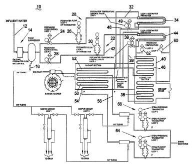
Figure 1 illustrates a schematic view of elements of a dual path steam
generator according to an embodiment of the invention.
Best Mode for Carrying Out the Invention
The following detailed description represents the best currently
contemplated modes for carrying out the invention. The description is not to
be
taken in a limiting sense, but is made merely for the purpose of illustrating
the
general principles of the invention.
Referring to Figure 1, a steam generation 10 may be represented in
schematic form as a dual fluid flow conduit or pass steam generator 10. The
steam generator 10 may have an influent water flow 12 that may be conditioned
14 and a portion diverted as controlled by diverter valve 16 or a variable
pressure regulated pump may be used for control of the speed of the pump.
The influent water may then be split to flow in a first conduit 20 and a
second
conduit 22. The volume of influent water flow12 in each conduit 20, 22 may be
controlled by a first flow valve 24 and first flow transmitter 26 and a second
flow
valve 28 and second flow transmitter 30.
A first water portion 32 may flow through a first preheater 34 and then
through a first element 36 of a convection section 40. A portion of the first
water portion 32 may be diverted as may be controlled by a first temperature
3

CA 02641252 2014-07-04
controlled valve 39 to flow through a second preheater 44 to preheat a second
water portion 42 in the second conduit 22. The preheater 34, 44 may be a
double walled pipe having the water portions 32, 42 flowing in an inner pipe
and
the diverted convection section water portions 38, 48 flowing in an outer
pipe.
The first diverted convection section water 38 may exit the second preheater
44
and merge with the first water portion 32 to inflow into the first radiant
section
50. A first steam flow channel 54 may exit the first radiant section 50 to
merge
with a second steam flow channel 56 to be discharged from the steam
generator 10.
In a like process the second water portion 42 may flow through the
second preheater 44 and a second element 46 of the convection section 40. A
portion may be diverted as second diverted convection section water 48 to flow

through the first preheater 34 and exit therefrom to merge with the second
water portion 42 to inflow into a second radiant section 52. A second steam
flow channel 56 may exit the second radiant section 52 to merge with the first

steam flow channel 54 to be discharged from the steam generator 10.
There may be temperature sensors 60, 62 to monitor water portions 32,
42 temperature intermediate the preheaters 34, 44 and the convection section
40. There may also be steam pressure measurement elements 64, 66 prior to
the merging of the steam flows 54, 56 for measuring steam quality.
The water portions 32, 42 flow rate may be controlled to be
approximately equal and the steam quality between the first steam flow 54 and
the second steam flow 56 may be controlled to be approximately equal by
controlling the outlet temperature of each preheater 34, 44.
The steam quality control may be implemented by a control system (not
shown) by controlling the amount of diverted convection section water 38, 48
flows through each preheater 34, 44 using temperature controlled valves 39,
49. This process may compensate for differences in the heat transfer
characteristics of the two conduits 20, 22 by transfer of a portion of heat
energy
from the water portion 32, 42 having the higher heat transfer to that having
the
lower heat transfer. The result may be that each steam flow 54, 56 may have
approximately the same steam quality and fluid flow rate.
4

CA 02641252 2008-07-31
WO 2007/076124 PCT/US2006/049260
While the invention has been particularly shown and described with
respect to the illustrated embodiments thereof, it will be understood by those

skilled in the art that the foregoing and other changes in form and details
may
be made therein without departing from the spirit and scope of the invention.

Dessin représentatif
Une figure unique qui représente un dessin illustrant l'invention.
États administratifs

Pour une meilleure compréhension de l'état de la demande ou brevet qui figure sur cette page, la rubrique Mise en garde , et les descriptions de Brevet , États administratifs , Taxes périodiques et Historique des paiements devraient être consultées.

États administratifs

Titre Date
Date de délivrance prévu 2015-09-15
(86) Date de dépôt PCT 2006-12-23
(87) Date de publication PCT 2007-07-05
(85) Entrée nationale 2008-07-31
Requête d'examen 2011-12-22
(45) Délivré 2015-09-15
Réputé périmé 2018-12-24

Historique d'abandonnement

Date d'abandonnement Raison Reinstatement Date
2012-12-24 Taxe périodique sur la demande impayée 2013-12-11

Historique des paiements

Type de taxes Anniversaire Échéance Montant payé Date payée
Rétablissement des droits 200,00 $ 2008-07-31
Le dépôt d'une demande de brevet 400,00 $ 2008-07-31
Taxe de maintien en état - Demande - nouvelle loi 2 2008-12-23 100,00 $ 2008-12-22
Taxe de maintien en état - Demande - nouvelle loi 3 2009-12-23 100,00 $ 2009-12-23
Taxe de maintien en état - Demande - nouvelle loi 4 2010-12-23 100,00 $ 2010-12-21
Requête d'examen 800,00 $ 2011-12-22
Taxe de maintien en état - Demande - nouvelle loi 5 2011-12-23 200,00 $ 2011-12-22
Rétablissement: taxe de maintien en état non-payées pour la demande 200,00 $ 2013-12-11
Taxe de maintien en état - Demande - nouvelle loi 6 2012-12-24 200,00 $ 2013-12-11
Taxe de maintien en état - Demande - nouvelle loi 7 2013-12-23 200,00 $ 2013-12-11
Taxe de maintien en état - Demande - nouvelle loi 8 2014-12-23 200,00 $ 2014-12-19
Taxe finale 300,00 $ 2015-05-27
Taxe de maintien en état - brevet - nouvelle loi 9 2015-12-23 400,00 $ 2016-05-31
Taxe de maintien en état - brevet - nouvelle loi 10 2016-12-23 250,00 $ 2016-05-31
Titulaires au dossier

Les titulaires actuels et antérieures au dossier sont affichés en ordre alphabétique.

Titulaires actuels au dossier
RUSSONIELLO, FABIO M.
BOPP, STEVEN DAVID
KLOTH, TERRY L.
Titulaires antérieures au dossier
S.O.
Les propriétaires antérieurs qui ne figurent pas dans la liste des « Propriétaires au dossier » apparaîtront dans d'autres documents au dossier.
Documents

Pour visionner les fichiers sélectionnés, entrer le code reCAPTCHA :


Pour visualiser une image, cliquer sur un lien dans la colonne description du document. Pour télécharger l'image (les images), cliquer l'une ou plusieurs cases à cocher dans la première colonne et ensuite cliquer sur le bouton "Télécharger sélection en format PDF (archive Zip)" ou le bouton "Télécharger sélection (en un fichier PDF fusionné)".

Liste des documents de brevet publiés et non publiés sur la BDBC .

Si vous avez des difficultés à accéder au contenu, veuillez communiquer avec le Centre de services à la clientèle au 1-866-997-1936, ou envoyer un courriel au Centre de service à la clientèle de l'OPIC.


Description du
Document 
Date
(yyyy-mm-dd) 
Nombre de pages   Taille de l'image (Ko) 
Page couverture 2009-02-11 2 66
Abrégé 2008-07-31 1 78
Revendications 2008-07-31 3 110
Dessins 2008-07-31 1 45
Description 2008-07-31 5 225
Dessins représentatifs 2008-07-31 1 40
Revendications 2014-07-04 3 82
Description 2014-07-04 5 205
Abrégé 2014-07-04 1 21
Dessins représentatifs 2015-08-18 1 26
Page couverture 2015-08-18 1 59
PCT 2008-07-31 1 54
Cession 2008-07-31 4 142
Poursuite-Amendment 2011-12-22 1 40
Poursuite-Amendment 2014-01-06 2 51
Poursuite-Amendment 2014-07-04 14 462
Paiement de taxe périodique 2015-05-27 1 38
Paiement de taxe périodique 2016-05-31 1 29

Listes de séquence biologique

Sélectionner une soumission LSB et cliquer sur le bouton "Télécharger la LSB" pour télécharger le fichier.

Si vous avez des difficultés à accéder au contenu, veuillez communiquer avec le Centre de services à la clientèle au 1-866-997-1936, ou envoyer un courriel au Centre de service à la clientèle de l'OPIC.

Soyez avisé que les fichiers avec les extensions .pep et .seq qui ont été créés par l'OPIC comme fichier de travail peuvent être incomplets et ne doivent pas être considérés comme étant des communications officielles.

Aucun fichier LSB n'a été fourni.