Sélection de la langue

Search

Sommaire du brevet 2704350 

Énoncé de désistement de responsabilité concernant l'information provenant de tiers

Une partie des informations de ce site Web a été fournie par des sources externes. Le gouvernement du Canada n'assume aucune responsabilité concernant la précision, l'actualité ou la fiabilité des informations fournies par les sources externes. Les utilisateurs qui désirent employer cette information devraient consulter directement la source des informations. Le contenu fourni par les sources externes n'est pas assujetti aux exigences sur les langues officielles, la protection des renseignements personnels et l'accessibilité.

Disponibilité de l'Abrégé et des Revendications

L'apparition de différences dans le texte et l'image des Revendications et de l'Abrégé dépend du moment auquel le document est publié. Les textes des Revendications et de l'Abrégé sont affichés :

  • lorsque la demande peut être examinée par le public;
  • lorsque le brevet est émis (délivrance).
(12) Brevet: (11) CA 2704350
(54) Titre français: PROCEDE DE REALISATION DE TESTS D'ACUITE VISUELLE
(54) Titre anglais: A METHOD FOR PERFORMING VISUAL ACUITY TESTING
Statut: Octroyé
Données bibliographiques
(51) Classification internationale des brevets (CIB):
  • A61B 3/113 (2006.01)
  • A61B 3/028 (2006.01)
  • A61B 3/032 (2006.01)
  • A61B 3/12 (2006.01)
(72) Inventeurs :
  • ROGERS, JOHN (Royaume-Uni)
  • MCLEAN, DUNCAN (Canada)
  • PEDRO, JUSTIN (Canada)
  • WEITZ, RISHARD (Canada)
(73) Titulaires :
  • OPTOS PLC (Royaume-Uni)
(71) Demandeurs :
  • OPKO INSTRUMENTATION (Etats-Unis d'Amérique)
(74) Agent: MARKS & CLERK
(74) Co-agent:
(45) Délivré: 2016-09-20
(86) Date de dépôt PCT: 2008-11-05
(87) Mise à la disponibilité du public: 2009-05-14
Requête d'examen: 2013-09-06
Licence disponible: S.O.
(25) Langue des documents déposés: Anglais

Traité de coopération en matière de brevets (PCT): Oui
(86) Numéro de la demande PCT: PCT/CA2008/001924
(87) Numéro de publication internationale PCT: WO2009/059400
(85) Entrée nationale: 2010-04-30

(30) Données de priorité de la demande:
Numéro de la demande Pays / territoire Date
60/985,465 Etats-Unis d'Amérique 2007-11-05

Abrégés

Abrégé français

L'acuité visuelle d'un patient est examinée en approchant un appareil d'imagerie confocale d'un il du patient. Des stimuli sont appliqués en différents points du champ de vision du patient tandis que ce dernier fixe un point. Les réponses du patient aux stimuli sont enregistrées avec le mouvement de l'il qui est suivi au moyen de l'appareil d'imagerie confocale. La position de ces stimuli sur la rétine est corrigée pour tenir compte d'un éventuel mouvement de l'il entre les stimuli.


Abrégé anglais


A visual acuity
examination is performed on a patient by
bringing a confocal imaging apparatus
up to a patient's eye. Stimuli at various
points in the patient's field of view are
generated while the patient fixates on a
point. The patient's responses to the stimuli
are recorded with the movement of the eye
with is tracked with the aid of the confocal
imaging apparatus. The position of said
stimuli on the retina is corrected to take
into account any movement of the eye
between stimuli.

Revendications

Note : Les revendications sont présentées dans la langue officielle dans laquelle elles ont été soumises.


The embodiments of the invention in which an exclusive property or privilege
is
claimed are defined as follows:
1. A method of performing a visual acuity examination on a patient, the
method
comprising the steps of:
bringing a confocal imaging apparatus up to a patient's eye having a retina;
presenting a display to the patient;
displaying stimuli at various points on the target on the display in the
patient's
field of view while the patient fixates on a point on the target;
recording the patient's responses to said stimuli;
creating a succession of images of the retina with said confocal imaging
apparatus
while displaying said stimuli;
comparing said successive images to track movement of the retina; and
creating a map of the patient's acuity field from the responses to said
stimuli
taking into account any movement of the retina between successive stimuli
determined
by comparing said successive images.
2. A method as claimed in claim 1, wherein said map is overlaid on a
confocal
image of the retina obtained with said confocal imaging apparatus.
3. A method as claimed in claim 1 or 2, wherein said confocal imaging
apparatus is
a combined Scanning Laser Opthalmoscope and Optical Coherence Tomograph
(SLO/OCT) apparatus, and said map is overlaid on a tomographical image of the
retina
obtained by using the OCT portion of the apparatus.
4. A method as claimed in any one of claims 1 to 3, wherein said stimuli
comprise
light flashes, and the intensity of said light flashes is varied to determine
the patient's
response over different regions of the retina.
5. A method as claimed in any one of claims 1 to 4, wherein a shape is
displayed to
the patient on said display, and the limit of visual acuity is determined by
having the
patient report the orientation of the shape.
6. A method as claimed in claim 5, wherein said shape is a C-shape.
6

Description

Note : Les descriptions sont présentées dans la langue officielle dans laquelle elles ont été soumises.

CA 02704350 2015-04-22
A method for p,rforming visual acuity testing
FIELD OF THE INVENTION
This invention relates to field of ophthalmological examination, and in
particular to a
method for performing micro-perimetry and visual acuity examinations of a
patient.
BACKGROUND OF THE INVENTION
Visual field tests designed to map a person's visual field and document the
level of
peripheral vision are a mainstay in ophthalmology. Such tests are used to
assess disease
and treatment progressions. Typically, the test consists of having the patient
respond
every time a flash of light is perceived while the patient looks straight
ahead, fixating
onto a point. Visual acuity is normally tested using charts projected onto a
wall where the
patient is asked to read letters..Perimetry examination are used to test point
locations on
the retina and are commonly performed using a HumphreyTM field analyzer.
A major drawback of both of these systems is the lack of fundus tracking. For
instance, if
someone has 20/200 vision in his or her macular, but 20/40 vision in his or
her periphery,
a standard visual field test will not discern the difference, or tell the
doctor what part of
the fundus the patient is using to fixate. The fundus is the interior part of
the eye opposite
the lens.
1

CA 02704350 2010-04-30
WO 2009/059400
PCT/CA2008/001924
A standard perimetry examination provides no tracking. Projecting stimuli to
patients
with poor fixation gives meaningless results if the patient moves his eye
between stimuli.
SUMMARY OF THE INVENTION
According to the present invention there is provided a method of performing a
visual
acuity examination on a patient comprising bringing a confocal imaging
apparatus up to a
patient's eye; displaying stimuli at various points in the patient's field of
view while the
patient fixates on a point; recording the patient's responses to said stimuli;
tracking
movement of the eye with said confocal imaging apparatus; and correcting the
position of
the stimuli on the patient's retina to take into account any movement of the
eye between
successive stimuli.
Thus, in accordance with an embodiment of the invention, SLO imaging from a
combined Scanning Laser Ophthalmoscope and Optical Coherence Tomography
(SLO/OCT) system is used to image the eye while stimuli are displayed to the
patient.
Software automatically tracks the motion of the eye during the examination.
This gives
the doctor valuable information, such as what parts of the eye the patient is
using to
fixate, helps ensure the accuracy of the test, and provides the doctor with an
excellent
fundus image for use in diagnosis.
As soon as the acuity or perimetry exam is complete, the patient can be
scanned using the
OCT portion of the system so the doctor can see structural information from
the patient's
eye by performing B-Scans, C-Scans, or obtaining a 3D tomography. The
functional
(perimetry and acuity) information can then be overlaid on the structural
information so
the doctor can see which structures in the eye correlate to visual loss.
2

CA 02704350 2014-05-07
Having functional and structural capabilities built into a single machine
means less
examination time is required for a patient, less training is required for the
operator, and
more accurate information can be delivered to the doctor.
According to an aspect of the present invention, there is provided a method of
performing
a visual acuity examination on a patient, the method comprising the steps of:
bringing a confocal imaging apparatus up to a patient's eye having a retina;
presenting a display to the patient;
displaying stimuli at various points on the target on the display in the
patient's
field of view while the patient fixates on a point on the target;
recording the patient's responses to said stimuli;
creating a succession of images of the retina with said confocal imaging
apparatus
while displaying said stimuli;
comparing said successive images to track movement of the retina; and
creating a map of the patient's acuity field from the responses to said
stimuli
taking into account any movement of the retina between successive stimuli
determined
by comparing said successive images.
BRIEF DESCRIPTION OF THE DRAWINGS
The invention will now be described in more detail, by way of example only,
with
reference to the accompanying drawings, in which:
Figure 1 is a picture of the retina showing the results of a perimetry exam;
Figure 2 is an OCT topographic image (False color indicates retinal thickness,
black and
white are OCT B-Scans);
Figure 3 shows the results of a perimetry examination overlaid on the
topographic image;
and
3

CA 02704350 2014-05-07
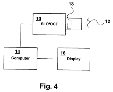
Figure 4 is a block diagram of an apparatus for performing a visual acuity
examination in
accordance with one embodiment of the invention.
DETAILED DESCRIPTION OF THE INVENTION
A commercially available combined SLO/OCT system is described, for example, in
US
patent No. 6,769,769. Such an SLO/OCT system is capable of making OCT images
of
the eye or retina as well as SLO or confocal microscopic images.
In accordance with an embodiment of the invention, a visual acuity examination
is
performed while the patient's eye motion is tracked using high resolution SLO
scans
generated by the SLO-OCT system. As shown in Figure 4, the SLO-OCT system 10
is
brought up to the patient's eye 12, and a series of SLO images of the retina
obtained by
3a

CA 02704350 2010-04-30
WO 2009/059400
PCT/CA2008/001924
scanning. The confocal images are created by computer 14 from the SLO scans
and
displayed on display screen 16.
The SLO-OCT system 10 is able to track movement of the retina by comparing
successive images. The tracking can be performed automatically in software in
the
computer 14 using any of a number of known algorithms suited for this purpose,
such as
a combination of edge detection and Hausdroff s algorithm for image alignment.
The
actual algorithm used is not important as long as it is able to accurately
track the eye
motion.
The SLO-OCT system 10 includes a high resolution display 18, controlled by the

computer 14, that the patient can see while being scanned. The high resolution
display 18
is used to create a fixation target for the patient to fixate on. The patient
is asked to fixate
on the target while the examination is performed by generating the stimuli at
various
points in the patient's field of view and at various intensities. For example,
if the patient
is looking at a central point, a flash may be generated at a location
described by polar
coordinates r1, 01, and the patient asked to indicate whether he can observe
this flash. The
intensity of the flash can be changed to determine the patient's
responsiveness at this
point. The process can then be repeated at different points, ri, 0.
The resulting tracking data obtained from the SLO-OCT system are then used
with the
display 18 to accurately place the perimetry stimuli on the same fundus
location for each
point tested taking into account any patient movement. Thus, based on the
patient's
responses, a map of the patient's acuity field, as shown in Figure 1, can be
created. By
taking into account the eye motion detected by the SLO imaging apparatus
between
scans, the data points can be correlated to the correct positions on the
patient's retina. For
4

CA 02704350 2010-04-30
WO 2009/059400
PCT/CA2008/001924
example, if the SLO imaging apparatus detects that the retina moved an amount
8x
between successive stimuli, the position of the later stimulus point on the
retina can be
adjusted to take this movement into account.
In addition, a tomographic three dimensional image, shown in Figure 2, can be
obtained
using the OCT portion of the apparatus, in which case the stimuli points can
be marked
on the 3D image as shown in Figure 3.
The display can also be used to display a Snellen 'C' in one of four
orientations (opening
of the C up, down, left, or right). In this test, the patient uses a hand-held
controller or
joystick to report the direction of the opening. When the patient can no
longer tell the
direction of the opening, he has passed the limit of their visual acuity. Any
number of
other letters or symbols can be used for the same purpose. The tracking data
obtained by
the SLO apparatus can be recorded to show which part of the eye the patient
was using to
fixate on the fixation point.
The invention takes advantage of the functional and structural information
that the SLO-
OCT system can generate. It may desirably use automatic alignment of SLO
images from
function and structural imaging to overlay perimetry or acuity results on B-
Scans, C-
Scans or topographies in the computer 14.
Aspects of the invention thus include a method for integrating micro-perimetry
exams
into a combined imaging SLO-OCT system, and a method for integrating acuity
exams
into a combined imaging SLO-OCT system.

Dessin représentatif
Une figure unique qui représente un dessin illustrant l'invention.
États administratifs

Pour une meilleure compréhension de l'état de la demande ou brevet qui figure sur cette page, la rubrique Mise en garde , et les descriptions de Brevet , États administratifs , Taxes périodiques et Historique des paiements devraient être consultées.

États administratifs

Titre Date
Date de délivrance prévu 2016-09-20
(86) Date de dépôt PCT 2008-11-05
(87) Date de publication PCT 2009-05-14
(85) Entrée nationale 2010-04-30
Requête d'examen 2013-09-06
(45) Délivré 2016-09-20

Historique d'abandonnement

Il n'y a pas d'historique d'abandonnement

Taxes périodiques

Dernier paiement au montant de 473,65 $ a été reçu le 2023-11-02


 Montants des taxes pour le maintien en état à venir

Description Date Montant
Prochain paiement si taxe générale 2024-11-05 624,00 $
Prochain paiement si taxe applicable aux petites entités 2024-11-05 253,00 $

Avis : Si le paiement en totalité n'a pas été reçu au plus tard à la date indiquée, une taxe supplémentaire peut être imposée, soit une des taxes suivantes :

  • taxe de rétablissement ;
  • taxe pour paiement en souffrance ; ou
  • taxe additionnelle pour le renversement d'une péremption réputée.

Les taxes sur les brevets sont ajustées au 1er janvier de chaque année. Les montants ci-dessus sont les montants actuels s'ils sont reçus au plus tard le 31 décembre de l'année en cours.
Veuillez vous référer à la page web des taxes sur les brevets de l'OPIC pour voir tous les montants actuels des taxes.

Historique des paiements

Type de taxes Anniversaire Échéance Montant payé Date payée
Le dépôt d'une demande de brevet 400,00 $ 2010-04-30
Taxe de maintien en état - Demande - nouvelle loi 2 2010-11-05 100,00 $ 2010-04-30
Taxe de maintien en état - Demande - nouvelle loi 3 2011-11-07 100,00 $ 2011-08-26
Taxe de maintien en état - Demande - nouvelle loi 4 2012-11-05 100,00 $ 2012-09-20
Requête d'examen 200,00 $ 2013-09-06
Taxe de maintien en état - Demande - nouvelle loi 5 2013-11-05 200,00 $ 2013-10-17
Taxe de maintien en état - Demande - nouvelle loi 6 2014-11-05 200,00 $ 2014-10-15
Taxe de maintien en état - Demande - nouvelle loi 7 2015-11-05 200,00 $ 2015-10-29
Enregistrement de documents 100,00 $ 2016-07-22
Taxe finale 300,00 $ 2016-07-25
Taxe de maintien en état - brevet - nouvelle loi 8 2016-11-07 200,00 $ 2016-11-02
Taxe de maintien en état - brevet - nouvelle loi 9 2017-11-06 200,00 $ 2017-09-01
Taxe de maintien en état - brevet - nouvelle loi 10 2018-11-05 250,00 $ 2018-10-15
Taxe de maintien en état - brevet - nouvelle loi 11 2019-11-05 250,00 $ 2019-10-28
Taxe de maintien en état - brevet - nouvelle loi 12 2020-11-05 250,00 $ 2020-10-29
Taxe de maintien en état - brevet - nouvelle loi 13 2021-11-05 255,00 $ 2021-10-27
Taxe de maintien en état - brevet - nouvelle loi 14 2022-11-07 254,49 $ 2022-11-02
Taxe de maintien en état - brevet - nouvelle loi 15 2023-11-06 473,65 $ 2023-11-02
Titulaires au dossier

Les titulaires actuels et antérieures au dossier sont affichés en ordre alphabétique.

Titulaires actuels au dossier
OPTOS PLC
Titulaires antérieures au dossier
MCLEAN, DUNCAN
OPKO INSTRUMENTATION
PEDRO, JUSTIN
ROGERS, JOHN
WEITZ, RISHARD
Les propriétaires antérieurs qui ne figurent pas dans la liste des « Propriétaires au dossier » apparaîtront dans d'autres documents au dossier.
Documents

Pour visionner les fichiers sélectionnés, entrer le code reCAPTCHA :


Pour visualiser une image, cliquer sur un lien dans la colonne description du document. Pour télécharger l'image (les images), cliquer l'une ou plusieurs cases à cocher dans la première colonne et ensuite cliquer sur le bouton "Télécharger sélection en format PDF (archive Zip)" ou le bouton "Télécharger sélection (en un fichier PDF fusionné)".

Liste des documents de brevet publiés et non publiés sur la BDBC .

Si vous avez des difficultés à accéder au contenu, veuillez communiquer avec le Centre de services à la clientèle au 1-866-997-1936, ou envoyer un courriel au Centre de service à la clientèle de l'OPIC.


Description du
Document 
Date
(yyyy-mm-dd) 
Nombre de pages   Taille de l'image (Ko) 
Description 2010-04-30 5 205
Dessins 2010-04-30 2 751
Revendications 2010-04-30 2 41
Abrégé 2010-04-30 1 60
Dessins représentatifs 2010-06-18 1 4
Page couverture 2010-07-06 2 37
Revendications 2014-05-07 1 42
Description 2014-05-07 6 222
Description 2015-04-22 6 212
Revendications 2015-04-22 1 45
Page couverture 2016-08-16 1 34
PCT 2010-04-30 3 133
Cession 2010-04-30 2 98
PCT 2010-05-04 1 38
Correspondance 2010-06-17 1 18
PCT 2010-08-03 1 44
Correspondance 2010-07-28 3 104
Poursuite-Amendment 2013-09-06 1 31
Poursuite-Amendment 2015-02-26 4 216
Poursuite-Amendment 2014-05-07 5 142
Poursuite-Amendment 2015-04-22 4 112
Taxe finale 2016-07-25 1 36