Sélection de la langue

Search

Sommaire du brevet 1288007 

Énoncé de désistement de responsabilité concernant l'information provenant de tiers

Une partie des informations de ce site Web a été fournie par des sources externes. Le gouvernement du Canada n'assume aucune responsabilité concernant la précision, l'actualité ou la fiabilité des informations fournies par les sources externes. Les utilisateurs qui désirent employer cette information devraient consulter directement la source des informations. Le contenu fourni par les sources externes n'est pas assujetti aux exigences sur les langues officielles, la protection des renseignements personnels et l'accessibilité.

Disponibilité de l'Abrégé et des Revendications

L'apparition de différences dans le texte et l'image des Revendications et de l'Abrégé dépend du moment auquel le document est publié. Les textes des Revendications et de l'Abrégé sont affichés :

  • lorsque la demande peut être examinée par le public;
  • lorsque le brevet est émis (délivrance).
(12) Brevet: (11) CA 1288007
(21) Numéro de la demande: 516808
(54) Titre français: CHICANE SUR TUYERE D'HELICE, ET METHODE CONNEXE
(54) Titre anglais: PROPELLER TUNNEL BAFFLE AND METHOD
Statut: Périmé
Données bibliographiques
(52) Classification canadienne des brevets (CCB):
  • 115/22
(51) Classification internationale des brevets (CIB):
  • B63H 5/16 (2006.01)
  • F01N 13/12 (2010.01)
  • B63H 21/32 (2006.01)
(72) Inventeurs :
  • SMALL, MARK S. (Etats-Unis d'Amérique)
(73) Titulaires :
  • SMALL, MARK S. (Etats-Unis d'Amérique)
(71) Demandeurs :
(74) Agent: JOHNSON, DOUGLAS S. Q.C.
(74) Co-agent:
(45) Délivré: 1991-08-27
(22) Date de dépôt: 1986-08-26
Licence disponible: S.O.
(25) Langue des documents déposés: Anglais

Traité de coopération en matière de brevets (PCT): Non

(30) Données de priorité de la demande:
Numéro de la demande Pays / territoire Date
06/769,438 Etats-Unis d'Amérique 1985-08-26

Abrégés

Abrégé anglais


Abstract of the Disclosure:

A marine craft having a propeller tunnel in which the
sidewalls of the tunnel are essentially parallel and
vertical and mate with a descending upper surface of the
tunnel which optionally can be divided into a transom
plate portion, engine plate portion, and bottom plate
portion. The bottom plate portion mates with the bottom
of the boat hull in a sharp line intersection. A
surfacing propeller and associated drive shaft is mounted
in the tunnel with a rudder positioned aft of the
surfacing propeller. Baffles are provided on the lateral
sides of the tunnel and terminate in a forward portion aft
of the bottom plate portion of the tunnel. Optionally the
exhaust can be vented onto the bottom plate portion of the
tunnel to augment the flow of air. The method of the
invention is directed to forcing the flow of air inside a
surfacing propeller tunnel on a boat to the end that
baffles provided on the lateral side are fed by air from
the transom portion of the baffle and induced by the
forward motion of the boat as well as the pneumatic effect
of the surfacing propeller portion which is not in the
water to force the air to go into the tunnel portion and
thereby minimize any negative pressure build-up which
would otherwise occur absent of venting. In addition the
method contemplates augmenting the pressure within the
tunnel by directing the exhaust to a forward portion of
the tunnel.

Revendications

Note : Les revendications sont présentées dans la langue officielle dans laquelle elles ont été soumises.


WHAT IS CLAIMED IS:

1. A propeller tunnel and baffle for a marine craft
comprising, in combination,

- essentially parallel sidewalls oriented
vertically forming the pocket portion of a tunnel for
positioning beneath and at the rear of a marine craft and
surrounding a surfacing propeller,

- said tunnel having an upper portion with
inclined segments terminating forwardly with a V-bottom
portion of the marine craft,

- baffles allowing venting provided at the
upper portion of the tunnel including the sides of the
tunnel for permitting air to pass through from the transom
side to the forward portion of the pocket,

- said baffles terminating aft of the forward
portion of the tunnel a sufficient distance to avoid
contact with water at planing speeds, and yet low enough to
channel the water through the baffles at low speeds.


2. In the propeller pocket of claim 1,

- means for exhausting engine exhaust forward of
the forward end of the baffles.

3. In the propeller tunnel of claim 1,
- the upper portion of said tunnel having three
portions,

- the first said portion being a transom plate
essentially parallel with the water line of the boat,

- the second portion being an engine plate
portion sloping downwardly toward the bottom,

- and a third bottom portion descending at a
steeper angle than the engine plate portion and joining
the hull,

- said bottom portion having a stuffing box for
the drive shaft contained therein.


4. In the propeller tunnel of claim 3,

- the center of gravity of the subject marine
craft being located 20% to 30% forward of the rear end
portion.


5. In the propeller tunnel of claim 3,

- said bottom plate having an angle in excess of
30° with that of the hull.


11


6. In the propeller tunnel of claim 3,

- said engine plate being essentially angled per
the optimum engine mount and gear box.


7. In the propeller tunnel of claim 3,

- said transom plate being 60% of the propeller
diameter above the keel line to the plate bottom.


12


8. In the propeller tunnel of claim 1,

- said tunnel length being approximately 300% of
the propeller diameter.


9. In the propeller tunnel of claim 1,
- the venting being provided to approximate 25%
of the projected area of the propeller.


13


10. In the propeller tunnel of claim 1,

- said total tunnel area in cross-section being
approximately 80% of the projected area of the propeller.


14


11. The method of venting a surfacing propeller tunnel
provided beneath and towards the transom of a boat hull
comprising the steps of,

- sloping the tunnel forwardly to terminate with
the bottom of the hull at a point where the stuffing box
of a drive shaft can be inserted into the forward portion
of the tunnel,

- providing a confined stream of air in open
communication with the transom portion of the boat which
terminates to the rear of the forward portion of the
tunnel,

- and reversing the flow of the air assisted by
the motion of the boat in combination with the pneumatic
drive portion of the surfacing propeller.


12. In the method of claim 11 above,

- assisting in the venting of the drive
tunnel by directing the engine exhaust into a forward
portion of the tunnel.


16


13. A surfacing propeller tunnel package where marine
craft comprising, in combination,

- a tunnel portion having sidewalls for mounting
in a recess in a rear portion of a propeller boat,

- said tunnel portion sidewalls having a top
plate portion defining the tunnel and terminating at a
portion to intersect with a V-bottom of a marine craft,

- said forward portion of the tunnel top
containing a stuffing box and a drive shaft for mounting
to a power train interiorly of the marine craft,

- said drive shaft being secured to the upper
rear portion of the tunnel top and having a surfacing
propeller on its rear portion,

- and means for securing said tunnel to a recess
in the marine craft in water tight integrity therewith.


17


14. A surfacing propeller tunnel package of claim 13,
comprising, in combination,

- said tunnel having a rear transom plate, a
mixed forward engine plate, and terminating with a back
plate.


18


15. In the drive tunnel of claim 6 above,

- means for directing the engine exhaust to a
forward portion of the upper portion of the tunnel.


19


16. In a planing hull marine craft having a propeller
pocket at the rear portion terminating in a sharp edge in the rear
one-third of the length of the hull, and having a surfacing prop
located within said propeller pocket, the improvement comprising,

- baffles forming vents on either side of the
propeller pocket in pneumatic communication with ambient air at
the rear portion of the boat hull, and terminating at the forward
portion of the propeller pocket but aft of the sharp edge
commencing the tunnel,
whereby the pneumatic portion dynamically of the interior of the
propeller pocket is relieved to ambient pressure at low speeds and
permits rapid acceleration to planing.


17. In the marine craft of claim 16 above,

- said propeller pocket having essentially
opposed parallel longitudinal sides, and having essentially an
upper portion which is planar proceeding from a mid-portion in the
transom downwardly and forwardly to the base of the hull.

18. In the marine craft of claim 16 above, wherein,

- said vents including an enclosed area in open
communication with ambient from above the base of the hull.


21


19. In the marine craft of claim 16 above, wherein,

- said vents are angular in cross-section with the
upper portion being wider than the lower portion to thereby
maximize the pneumatic capacity of the vents commensurate with
propeller clearance.


22

Description

Note : Les descriptions sont présentées dans la langue officielle dans laquelle elles ont été soumises.


` 128~30~7

TITLE: PROPELLER TUNNEL BAFFLE A~'D METHOD

Field of ~,h _Invention: The present invention relates to
powered marine craft, and more particularly the high speed
varie,ies. Specifically it is directed .o high speed
wa,er craft which use a surfacing propeller mounted in a
propeller tunnel. The prior art can be located in Class
440, subclasses 66-70.

Summary of the Prior Art: The use of propeller tunnels is
not new. This is true in both water craft and even the
shrouding of aircraft. The propeller tunnel permits
recessing the propeller at least in part interiorly of the
projected area of the hull. Numerous problems arise with
curren, surfacing propeller applications including
dangerous exposure of the propeller. Another problem
relates to the steering torque and avoiding the same.
Most importantly, however, at low speeds there is
cavitation and low thrust and water pile up at the transom
in reverse. Accordingly achieving a planing configuration
conswmes considerable excess power, results in inefficient
fuel consumption, and delays the boat when used as a
pursuit ship or racing ship in getting up into a planing
configuration and reaching the maximum intended speed.
Examples of the prior art patent may be seen in the
following: U.S. Patent Nos. 2,434 700: 3,702,485;
RE23,105; RE38,522; 130,391; 807,769; 815,270; 1,081,876;
1,117,357; 1,262,942; 1,401,963; 2,138,831; 3,450,090;
4,031,846; 4,363,630; 4,383,828; 22,080; Japanese Patent
No. 55-156795(A); British Patent No. 769,307; British
Applica,ion Nos. 2,075,452(A) and 2,055,080(A). In particular
the patents 2,434,700 and 3,702,485 relate to the type of
tunnel involved.

Summary of the Invention: The present invention is
_. __ _ _____
directed to a marine craft having a propeller tunnel in


~k

~8()~7'

which the sidewalls of the tunnel are essentially parailel
and vertical and mate with a descending upper surface of
the tunnel which optionally can be divided into a transom
plate portion, engine plate portion, and bottom plate
portion. The bottom plate portion mates with the bottom
of the boat hull in a sharp line intersection. A
surfacing propeller and associated drive shaft is mounted
in the tunnel with a rudder positioned aft of the
surfacing propeller. Baffles are provided on the lateral
sides of the tunnel and terminate in a forward portion aft
of the bottom plate portion of the tunnel. Optionally the
exhaust can be vented onto the bottom plate portion of the
tunnel to augment the flow of air, quiet engine and draw
exhaust from engine. The method of the invention is
directed to forcing the flow of air inside a surfacing
propeller tunnel on a boat to the end that baffles
provided on the lateral side are fed by air from the
transom portion of the baffle and induced by the forward
motion of the boat as well as the pneumatic effect of the
surfacing propeller portion which is not in the water to
force the air to go into the tunnel portion and thereby
minimize any negative pressure build-up which would
otherwise occur absent of venting. In addition the method
optionally contemplates augmenting the pressure within the
tunnel by directing the exhaust to a forward portion of
the tunnel.

In view of the foregoing it is a principal object of the
present invention to provide a vented boat tunnel in which
the tunnel utilizes a surfacing propeller and venting the
same to supply ambient air circulating to the forward
portion of the tunnel and then rearwardly over the
non-submerged portion of the surfacing propeller.

Another object of the present invention looks to the
development of a tunnel for a surfacing propeller in which

--" 128~300~

the major portion of the surfacing propeller is within or
adjacent the tunnel, and in which baffles provide for
venting the tunnel to permit accelerating the boat and
maintaining planing speeds.

Yet another object of the present invention looks to the
provision of a surfacing propeller tunnel which permits
reducing the angle with horizontal that the drive shaft
for the surfacing propeller makes thereby reducing the
component which would tend to drop the bow portion of the
boat into the water when underway.

Brief Description of the Drawin~s: Further objects and
_ _ _ __.____ __________________ _
advantages of the present invention will become apparent
as the following description of an illustrative embodiment
proceeds, taken in conjunction with the accompanying
drawings, in which:

FIG. 1 is a perspective view of the rear portion of a boat
having a surfacing propeller and tunnel mount for the
propeller;

FIG. 2 is a side view of the same boat as shown in FIG. 1
in essentially the same scale:

FIG. 3 is a bottom view in enlarged scale of the boat
shown in FIGS. 1 and 2 focusing on the construction of the
tunnel and showing the flow of air in alternative forms,
the form when cruising, and the form when idling;

FIG. 4 is a longitudinal section view, in part, showing
the interior of the propeller tunnel and the engine mount
in the slow speed configuration;

FIG. 5 is a view from the same perspective as FIG. 4 but
showing the boat in its planing or crusing configuration;
and


1288007

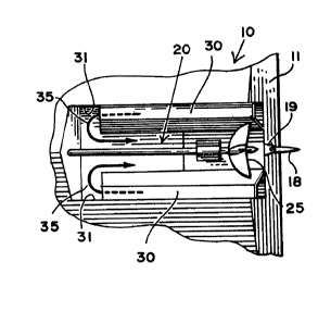
FIG~ 6 is a perspective view taken from underneath and
behind the surfacing propeller showing the interior
portions of the tunnel.

F`IG. 7 showing venting from upright tubes taking air from
hull interior or deck.

Descri_tion of the Preferred Embodiments:
____ ___ _

_~aratus: In FIG. 1 it will be noted that a boat 10 is
shown having a relatively conventional transom 11, and
curvilinear sides 12 above keel 13 moving forward to a bow
14. The underneath portion of the boat is a V~bottom 15
with a keel 13 and rudder assembly 16 exterior and aft of
the transom 11. The rudder assembly 16 includes the
cantileverly supported rudder 18 which depends from a
rudder mount 19 which, in turn, is mounted to the transom
11. The rudder can be of any convention means.

A tunnel 20 is provided underneath the V~bottom 15.
Turning now to FIGS. 5, 6 and 7, it will be seen that the
tunnel has an upper surface which includes a transom plate
portion 21, an engine plate portion 22 which slopes
downwardly from the transom plate portion 21 which is es-
sentially parallel to the path of travel, and terminating
in a bottom plate 24 which intersects the V~bottom 15 of
the boat in a relatively sharp line, particularly as seen
in FIG, 6.

A surfacing propeller 25 is mounted interiorly of the
tunnel and is driven by a drive shaft 26. The drive shaft
26 is mounted by a shaft mount to the transom plate
portion 21 of the tunnel 20. A stuffing box 29 in the
engine plate portion 22 of the tunnel 20 provides access
to the drive assembly interiorly of the boat hull.

~2~38007
In accordance with the invention baffles 30 are provided
at either side and the top of the tunnel 20, and intersect
the tunnel sides 31 of the tunnel. The interior portion of
the baffles includes a baffle channel 32. The front
porSion of the baffle channel 34 is located aft of the
lbottom plate 24 of the tunnel 20. As noted particularly
in FIG. 6, the baffles 30 are trapezoidal in configuration
with the rear portion opening through the transom 11. The
forward portion of the baffle 34 opens at a position
slightly above the plane of the drive shaft 26 and scoops
water at slow speeds, but is proportioned to always be
above the water at higher speeds.

As noted interiorly of the boat in FIGS. 4 and S an engine
40 is mounted above the engine plate 22 of the top of the
tunnel 20. An engine drive shaft 41 extends forwardly to
a gear box 42. Optionally, as shown in FIG. 4, the engine
exhaust 44 is routed to the forward portion of the engine
plate 22 of the tunnel 20, and as shown in FIG. 6, exhaust
ports 45 are located just aft of the bottom plate 24 of
the tunnel. Also shown in phantom lines is the outline
for a drive package and tunnel insert for conversion of
existing boats.

Center_of G_a ity: When establishing the center of
gravity for this type of craft there are several important
considerations. The surfacing type propeller has
significant lift and effects the dynamic center of
gravity. The absence of the bottom in the area of the
tunnel as well as the level of the water and the air
pressure in the tunnel have an effect on the dynamic
center of gravity. The aerodynamic, hydrodynamic and drag
forces are similar to other planing hulls. When the
differences are considered this type of system requires a
nominal center of gravity of only 20 to 30 percent of hull
length forward of the transom. This changes with hull
design, speed of craft and horsepower.


~288~)07

Plate Len~ths: The length of the plates mentioned are
____ __ _ _ _
proportioned to the size of craft and vary with the
Eollowing considerations:

~30ttom Plate 24: The bottom plate intersects the bottom
at an angle greater than 30 degrees to promote separation
of the flow stream at slow speeds. The length of the
plate is appropriate to accommodate the shaft log with a
minimum recommended vertical height of 25 percent of the
propeller diameter.

Engine Plate 22: The engine plate length and angle are
tailored to the engine configurations. The angle may be
less than the bottom plate to parallel to the bottom of
the hull terminating at the transom plate.

Transom Plate 21: The transom plate angle is to be
parallel to the hull bottom at an elevation that allows 60
percent of the propellor diameter vertically from the keel
line to the bottom of the plate. The length of the
transom plate is determined by the rudder, strut, and
propeller location. It is terminated at the forward end
at the engine plate. The transom plate may terminate at
its intersection with the bottom plate if the engine
configurations allow. The rudder may be installed in the
conventional manner under the hull if room permits or aft
of craft.

Overall Tunnel 20 Length: The nominal tunnel 20 length
for this type of system is 300 percent of the propeller
diameter. Shorter configurations will inhibit
acceleration and reduce tracking stability gained from the
tunnel walls. Longer configurations will increase
propeller submersion reducing top speed.

1288007
Propeller Location: The propeller is located to meet
several of the following conditions:

1. The spray from the propeller must not cover the baffle
inlets.

2. The minimum distance from the leading edge of the
tunnel to the rear face of the propeller circle is to be
300 percent of the propeller diameter.

3. The nominal elevation of the propeller center line is
to be coincident with the keel line. Up from this
position increases top speed and craft crab angle. Down
from this position has opposite effect.

4. Under dynamic conditions the propeller lift is
included in the dynamic center of gravity and allows
tuning of the craft for a window of speed. For speeds
other than this window the attitude of craft can be
adjusted by conventional trimming techniques.

Tunnel and Vent Areas: The area of the tunnel 20 and the
vents (baffle channels 32) are to be constructed with the
following considerations:

1. The venting area required is a minimum of 25 percent
of the propeller circle area when the vents are in
communication with ambient air. This venting area can be
divided between the baffles and the vent tubes or
contained entirely by one venting system.

2. The total area of the tunnel including the rear vents
in the plane of the transom of the boat is to be 80
percent of the propeller circle area.

T_e Met_o_: The method of the present invention is
directed to the flow of air interiorly of a surfacing


~Z88007
propeller tunnel in a water craft. The method is performed
by directing a flow of ambient air from the transom
forward to the front portion of the surfacing propeller
tunnel. Thereafter the air is permitted to reverse
rearwardly and be engaged and accelerated by the
non-submerged portion of the surfacing propeller which is
in the air. Optionally the negative pressure tendency of
the propeller tunnel is offset by confining the engine
exhaust and directing the same interiorly of the tunnel.

Although particular embodiments of the invention have been
shown and described in full here, there is no intention to
thereby limit the invention to the details of such
embodiments. On the contrary, the invention is to cover
all modifications, alternatives, embodiments, usages and
equivalents of the subject invention as fall within the
spirit and scope of the invention, specification, and the
appended claims.

Dessin représentatif
Une figure unique qui représente un dessin illustrant l'invention.
États administratifs

Pour une meilleure compréhension de l'état de la demande ou brevet qui figure sur cette page, la rubrique Mise en garde , et les descriptions de Brevet , États administratifs , Taxes périodiques et Historique des paiements devraient être consultées.

États administratifs

Titre Date
Date de délivrance prévu 1991-08-27
(22) Dépôt 1986-08-26
(45) Délivré 1991-08-27
Expiré 2008-08-27

Historique d'abandonnement

Il n'y a pas d'historique d'abandonnement

Historique des paiements

Type de taxes Anniversaire Échéance Montant payé Date payée
Le dépôt d'une demande de brevet 0,00 $ 1986-08-26
Taxe de maintien en état - brevet - ancienne loi 2 1993-08-27 50,00 $ 1993-08-26
Taxe de maintien en état - brevet - ancienne loi 3 1994-08-29 50,00 $ 1994-07-06
Taxe de maintien en état - brevet - ancienne loi 4 1995-08-28 50,00 $ 1995-07-10
Taxe de maintien en état - brevet - ancienne loi 5 1996-08-27 75,00 $ 1996-08-23
Taxe de maintien en état - brevet - ancienne loi 6 1997-08-27 75,00 $ 1997-07-28
Taxe de maintien en état - brevet - ancienne loi 7 1998-08-27 75,00 $ 1998-07-27
Taxe de maintien en état - brevet - ancienne loi 8 1999-08-27 75,00 $ 1999-07-19
Taxe de maintien en état - brevet - ancienne loi 9 2000-08-28 75,00 $ 1999-07-19
Taxe de maintien en état - brevet - ancienne loi 10 2001-08-27 100,00 $ 1999-07-19
Taxe de maintien en état - brevet - ancienne loi 11 2002-08-27 100,00 $ 1999-07-19
Taxe de maintien en état - brevet - ancienne loi 12 2003-08-27 100,00 $ 1999-07-19
Taxe de maintien en état - brevet - ancienne loi 13 2004-08-27 100,00 $ 1999-07-19
Taxe de maintien en état - brevet - ancienne loi 14 2005-08-29 100,00 $ 1999-07-19
Taxe de maintien en état - brevet - ancienne loi 15 2006-08-28 200,00 $ 1999-07-19
Taxe de maintien en état - brevet - ancienne loi 16 2007-08-27 200,00 $ 1999-07-19
Titulaires au dossier

Les titulaires actuels et antérieures au dossier sont affichés en ordre alphabétique.

Titulaires actuels au dossier
SMALL, MARK S.
Titulaires antérieures au dossier
S.O.
Les propriétaires antérieurs qui ne figurent pas dans la liste des « Propriétaires au dossier » apparaîtront dans d'autres documents au dossier.
Documents

Pour visionner les fichiers sélectionnés, entrer le code reCAPTCHA :


Pour visualiser une image, cliquer sur un lien dans la colonne description du document. Pour télécharger l'image (les images), cliquer l'une ou plusieurs cases à cocher dans la première colonne et ensuite cliquer sur le bouton "Télécharger sélection en format PDF (archive Zip)" ou le bouton "Télécharger sélection (en un fichier PDF fusionné)".

Liste des documents de brevet publiés et non publiés sur la BDBC .

Si vous avez des difficultés à accéder au contenu, veuillez communiquer avec le Centre de services à la clientèle au 1-866-997-1936, ou envoyer un courriel au Centre de service à la clientèle de l'OPIC.


Description du
Document 
Date
(yyyy-mm-dd) 
Nombre de pages   Taille de l'image (Ko) 
Dessins représentatifs 2001-11-16 1 11
Dessins 1993-10-29 2 97
Revendications 1993-10-29 14 153
Abrégé 1993-10-29 1 45
Page couverture 1993-10-29 1 12
Description 1993-10-29 8 298
Taxes 1996-08-23 1 41
Taxes 1995-07-10 1 32
Taxes 1994-07-06 1 30
Taxes 1993-08-26 1 28