Note : Les descriptions sont présentées dans la langue officielle dans laquelle elles ont été soumises.
2 ~
DIAGNOSTIC DEVICE FOR GAS TURBINE IGNITION SYSTEM
Technical Field
The invention generally relates to ignition systems
for gas turbine engines and, more particularly, to
monitoring and diagnostic devices for such systems.
Backqround of the Invention
The monitoring of ignition systems for gas turbine
engines is of particular interest because such systems are
of critical importance to the safe operation of aircraft
incorporating these types of engines. By monitoring the
performance of ignition systems in gas turbine engines, an
indication that the system is malfunctioning can be
obtained. By providing an indication of a malfunctioning
ignition system, a measure of safety is obtained that can
be of particular importance in ensuring the ignition
system is capable of restarting an engine after a flameout
l~â~ UrL 2~, 0~ to ir.i' ~c ~ C2 ~ e ~,iv~ ~v
the next flight.
In monitoring ignition systems of gas turbine
engines, the state of health of the igniter plug has in
the past been the focus since the igniter plug is the
component of the ignition system with the shortest average
useful life. Failure or malfunctioning of other
components of the ignition system, however, may occur and
39-413/nas
the typical monitoring system fails to identify failures
or malfunctioning of these other components. Indeed, some
monitoring devices may actually falsely indicate a
properly operating ignition system when the system is in
fact malfunctioning or failing, others may indicate a
failure when none exists causing unnecessary maintenance.
An ignition sequence is typically initiated by a
narrow high voltage pulse generated by an exciter circuit.
For a successful ignition, the high voltage pulse is
discharged at the igniter plug, thereby generating a
spark. There have been attempts to analyze the voltage
pulse from the exciter and the following voltage waveform
generated by the spark in order to diagnose the health of
an ignition system. In the past, however, such monitoring
systems could only provide an indication of the health of
the igniter plug and failed to monitor or diagnose the
state of health of other components of the ignition system
that may lead to failure of the igniter plug.
For exampie, '~.~. Pate..t No. A ~ 750,3~1 t~ Skerritt
discloses a monitoring device that senses the electric
field generated by a signal at the input to the igniter
plug of an ignition system. The monitoring device
receives the signal generated by the electric field and
detects if the input signal to the plug is maintained
longer than a predetermined time period and above a
predetermined voltage level. If the input signal is
39-413/nas
2~4~7~
~,
maintained longer than the predetermined time period, the
device indicates the plug is deteriorating. If the
voltage of the input signal fails to reach the
predetermined level, however, the monitor of the Skerritt
patent also interprets this failure as a deteriorating
plug when in fact the exciter may be degraded and the
igniter is functioning properly.
In addition to measuring the width of the high
voltage pulse, the monitoring device in the Skerritt
patent also measures the energy discharged through the
plug during the spark event. If the total energy
delivered in the spark event signal is satisfactory and
the signal to the plug is not too long, the monitoring
device provides a pulse output, indicating that the
igniter plug is operating properly.
Although measurement of the total energy delivered to
the plug in response to the high energy pulse is a useful
complement to the measurement of pulse duration, the two
...easu-2.u2n~s f2' 1 'c pr~vid- the uce~ with ~nythlng ot~her
than a general indication that the ignition system is
malfunctioning. More specifically, the measurements of
the Skerritt monitoring device do not distinguish between
a failing device for discharging the high energy pulse
(i.e., the igniter plug) and a failing device for
generating the high energy pulse (i.e., the exciter).
--3--
39-413tnas
20-17~7~
Summary of the Invention
I~ is the primary object of the invention to monitor
the health of each of the igniter plug and the exciter
circuit in an ignition system by detecting abnormal
conditions in the waveforms of the system associated with
a spark event.
It is also an important object of the invention to
detect malfunctioning of the igniter plug at a location
within the ignition system that is isolated from the
extreme environment of the igniter plug and is implemented
without the need of an expensive sensor coupling to the
igniter plug or its input leads; but rather by sensing
perturbations in the waveforms of existing signals. In
this connection, it is also an object of the invention to
monitor the state of health of the igniter plug at a
location within the ignition system that is remote from
the plug itself so that the monitoring device can be
effectively incorporated into the same apparatus as the
exciter circuitry and totally isolated from the extreme
environment of the igniter plug.
It is a related object of the invention that no
additional wires or connectors are required on the
downstream side of the exciter in order to accomplish the
diagnostic monitoring.
It is yet another important object of the invention
to diagnose the state of health of the ignition system by
39-413/nas
2~47~ 1~
distinguishing between the failure of the plug and the
failure of the exciter circuit. In this regard, it is a
related object of the invention to prevent false diagnosis
of the state of health of the igniter by requiring the
exciter to be diagnosed as healthy before the igniter is
diagnosed as failed.
It is another important object of the invention to
accurately monitor the health of both the igniter plug and
the exciter circuit for an ignition system by
distinguishing between actual failure of the plug or
exciter circuit and the occasional irregularities in the
high energy pulse that may occur as a result of normal
operation in the severe environment of a turbine engine.
It is another important object of the invention to
provide an indication of the impending failure of an
igniter plug in an ignition system so as to provide an
opportunity for initiating preventive maintenance.
It is still another ob~ect of the invention to
m.r.im~e 'he number c~ 'eads regu7red to co~municate to a
remote location the diagnostic information derived from
the monitoring of the ignition plug and exciter circuit.
It is another object of the invention to provide a
monitoring system for an ignition system that is easily
adapted as a transportable automatic test eguipment (ATE)
separate from the turbine engine and its ignition system.
39-413/nas
2~7~
Other objects and advantages will become apparent
with reference to the following detailed description when
taken in conjunction with the drawings.
The invention achieves the foregoing objects by
providing a monitoring device for an ignition system of a
gas turbine engine that comprises an exciter detector and
an igniter detector, each monitoring characteristics of
high energy pulses delivered from an exciter to an output
circuit of the ignition system for generating a spark at
an igniter plug. In response to the monitoring of the
high energy pulses, the exciter detector provides an
indication of the exciter's state of health and the
igniter detector provides an indication of the igniter
plug's state of health.
In the exciter detector, the voltage levels of the
high energy pulses are monitored to determine whether they
are persistently less than a predetermined value
representing a nominal minimum voltage generated by the
exciter when healthy. In the igniter detector, the rate
of discharge for the high energy pulses from the exciter
into an output circuit of the ignition system is monitored
to determine whether the rate of discharge is persistently
less than a predetermined rate representing a nominal
minimum rate of discharge for a healthy igniter plug.
In order for the monitoring device to sense the high
energy signals from the exciter, a high impedance voltage
--6--
39-413/nas
~4'i~
.,
divider network connects the output of the exciter to
ground. A signal from a node of the voltage divider
provides the input signal for each of the exciter and
igniter detectors. For purposes of economy, a safety
resistor, typically present at the output of the exciter,
may be incorporated into the voltage divider.
The exciter and igniter detectors are responsive to
the high energy pulses generated by the exciter and the
discharging of the high energy pulses into the output
circuit. In a properly operating ignition system, a
healthy exciter produces high energy pulses of at least a
predetermined minimum voltage. For a healthy igniter
plug, the output circuit stores the high energy pulse into
an inductor and quickly discharges the energy of the pulse
as a spark at the igniter plug. If the igniter plug fails
to spark, the input to the output circuit appears as a
virtual open circuit to the high energy pulses and the
pulses discharge through the voltage divider network. The
rate of discharge for the high energy pulses through the
voltage divider network is much less than the rate of
discharge for the pulses through the igniter plug.
Therefore, the ignition detector monitors the rate of
discharge of the high energy pulses and determines from
that rate the igniter plugs state of health.
To prevent the false indication of a failed igniter
plug as a result of the upstream failure of the exciter,
39-413/nas
2 ~ ? ~
,..~
the response times of the exciter and igniter detectors
are such that the exciter detector response is
significantly faster than the igniter detector. A
diagnostic output circuit responsive to the exciter and
igniter detector provides the user of the monitoring
device with an indication of the state of health of the
ignition system and ensures against a false indication of
a failed igniter plug by ignoring an indication of a
failed igniter plug if the exciter detector is also
providing an indication of a failed exciter.
The monitoring device of the invention may be used to
monitor a single channel of an ignition system -- i.e., an
exciter and associated output circuit and igniter plug.
Alternatively, the monitoring device may be used in
connection with an ignition system comprising multiple
channels. For a multiple channel ignition system, the
monitoring device includes exciter and igniter detectors
for each channel. In order to minimize the cabling
necessary to communicate the diagnostic signals of the
monitoring device to a display in a multi-channel system,
the signals from the various exciter and igniter detectors
are first encoded and then communicated to a remote
display via a thin cable. At the remote display, the
signals are decoded and the state of health of the
ignition system is indicated to a user.
39-413/nas
2~ 7~?~
In an alternative embodiment, the diagnostic system
of the invention may ~e placed in a stand alone automatic
test equipment (ATE) environment so that it can be
incorporated into a structured maintenance routine. The
ATE may include an exciter and output circuit in order to
deliver the same type of high energy pulses provided an
igniter plug by the ignition system. A technician or
other maintenance personnel disconnects the igniter plug
from the ignition system either by physically removing the
plug or disconnecting the plug at its cable connection to
the output circuit of the ignition system. Once
disconnected, the igniter plug can be connected to receive
high energy pulses from the exciter and output circuit
associated with the ATE apparatus and the monitoring
device will report to the maintenance personnel the state
of health of the igniter plug.
In addition to detecting persistent failure of the
exciter and igniter plug of a channel, the monitoring
device may also detect the intermittent failure of either
the exciter or igniter plug and report a diagnosis and
response thereto.
Brief Descri~tion of the Drawinqs
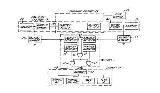
FIGURE 1 is a block diagram of the monitor of the
invention in its intended environment of an ignition
system in a turbine engine;
39-413/nas
2 ~
FIG. lA is a schematic diagram of an exemplary output
circuit for the ignition system of FIGURE l;
FIGS. 2A-2B are exemplary voltage waveforms for a
high energy pulse delivered to an igniter plug by an
exciter circuit in the ignition system of FIGURE 1, where
FIG. 2A illustrates an exemplary waveform associated with
a healthy igniter and FIG. 2B illustrates an exemplary
waveform associated with a failed igniter;
FIG. 3 is a schematic diagram of the monitor of FIG.
1 implemented in an analog manner and in accordance with a
preferred embodiment; and
FIG. 4 is a schematic block diagram of a digital
circuit for monitoring the state of health of the igniter
plug in accordance with the invention such that both
actual failure and impending failure of the plug may be
diagnosed.
While the invention will be described in some detail
with reference to a preferred embodiment and an
alternative embodiment illustrated in ine drawings, it is
to be understood that this description is not intended to
limit the scope of the invention. On the contrary,
applicant intends the scope of the invention to cover all
alternatives, modifications and equivalents that fall
within the spirit and scope of the appended claims.
--10--
39-413/nas
2~4 7~
Detailed Description of the Preferred Embodiment
Turning to the drawings and referring first to FIGURE
1, a monitoring device 11 according to the invention is
responsive to a series of voltage signals derived from a
corresponding series of high energy pulses provided at the
output of each of a pair of exciters 13 and 15 of an
ignition system 17 for use by a pair of output circuits 19
and 21 and igniter plugs 1 and 2 to generate spar~s. Each
one of the pairs is commonly referred to as a channel.
Although the ignition system 17 as illustrated in FIGURE 1
includes two channels, it will be appreciated that the
ignition system may include only one channel or
alternatively a plurality of channels.
As is well known in the art, each of the exciters 13
and 15 and output circuits 19 and 21 is typically located
externally from the turbine engine 23, whereas each of the
igniter plugs 1 and 2 is of course located within a
combustion chamber of a turbine engine 23 as suggested by
FIGURE 1. A fuel source 25 provides fuel to the
combustion chamber within the engine 23 where it is
ignited by spar~s generated by each of the igniter plugs 1
and 2. The two channels of an exciter, output circuit and
igniter plug is a typical installation in a turbine engine
used in aircraft since it provides a redundancy that
protects against failure of the ignition system in flight.
Because the two channels of an exciter, output circuit and
39-413/nas
2 ~ ? ~
igniter plug are redundant, those skilled in the art of
ignition systems for gas turbine engines will appreciate
that the following description with reference to one
channel of the exciter 13, output circuit 19 and plug 1
applies equally well to the other channel of exciter 15
and igniter circuit 21.
Each of the output circuits 19 and 21 comprises a
unipolarity diode-D1, an output inductor L1 and a high
voltage output connector 54 as illustrated in FIG. lA.
The output connector 54 is a conventional high voltage
coupling that is useful in connection with an alternative
application of the invention. Specifically, a monitoring
device like the monitoring device 11 of FIG. 1 may be
incorporated into automatic test equipment (ATE) that
reproduces the function of the ignition system 17 so as to
provide high energy ignition pulses to either of the
igniter plugs 1 or 2. The state of health of each igniter
plug 1 and 2 may be checked by a technician at any time
merely by disconnecting the plug from the ignition system
and connecting it to an output of the ATE that provides
calibrated high energy pulses. The monitoring device
internal to the ATE functions the same as the monitoring
device 11 and provides the technician with a means to
quickly check the ignition system to ensure it is
functioning properly. Although not as convenient as
disconnecting the igniter plug at the high voltage
-12-
39-413/nas
2 ~ 7 ~
connector, the ATE apparatus may alternatively incorporate
a socket for receiving igniter plugs such that the
technician physically removes the plug from the ignition
system and places it in the ATE for testing its state of
health.
As can be appreciate from FIG. lA, each of the output
circuits 19 and 21 provides for unipolar discharging of
the high energy pulses from the exciters 13 and 15. The
invention may also be used in connection with a bipolar
discharge, however, and in this regard the unipolar
configuration of FIG. lA is only illustrative. In either
bipolar or unipolar output circuits, the ignition event
may be divided into two discharge events. The first
discharge event occurs when a storage capacitor (not
shown) of the exciter 13 or 15 discharges a high energy
pulse into the output circuit. The second discharge event
occurs when the inductor L1 stores the energy from the
pulse and discharges it through the igniter plug and diode
D1.
When the igniter plug 1 fails, it typically fails
such that the output circuit 19 appears as an open circuit
with respect to the exciter 13. In order to dissipate the
high energy pulse from the output of the exciter 13 when
the igniter plug 1 fails, a resistor is commonly employed
to shunt the pulse to ground. Such resistors are often
called "safety" resistors. The safety resistors typically
-13-
39-413/nas
- 2 ~ 3
each have a value of lk to 10k Ohms. When the igniter
plug 1 fires, the impedance of the arc is very small (i.e.
usually measured in milliohms), approaching a short
circuit, and the discharge of the exciter 13 is very rapid
because the time constant of the output circuit 19 is
short. If the igniter plug 1 fails to fire (an arc fails
to form due to insufficient ionization), then the
impedance of the output circuit 19 remains very large,
approaching an open circuit, and the discharge of the
exciter 13 must seek an alternative path that is provided
by the safety resistor. Because the safety resistor has a
high resistance value relative to the low resistance at
the gap of the igniter plug 1 when a spark is generated,
the rate of discharge of the exciter 13 through the
resistor is long compared to the rate of discharge when a
healthy spark has been generated.
Referring briefly to the exemplary discharge
waveforms of FIGS. 2a and 2b, a healthy ignition system 17
discharges the high energy pulse from the exciter 13 into
the output circuit 19 in approximately three (3)
microseconds as indicated by the waveform 31 in FIG. 2a.
The normal output of the exciter 13 is a narrow high
voltage pulse occurring at a regular interval (i.e., 3
microseconds, 2500 volts, once per second). Repeated high
energy pulses are typically automatically generated by the
exciter 13 in order to provide a series of ignition sparks
-14-
39-413/nas
2 ~
that protect against a flameout of the engine 23 during
critical times such as landing and takeoff of the
associated aircraft where a manual initiation of an
ignition to restart the engine cannot be safely done.
It will be appreciated by those skilled in ignition
systems for gas turbine engines that the waveform 31 is
only the initial portion of the full waveform for an
entire discharge event, which is typically 150
microseconds long. When the waveform 31 crosses a
reference ground for the exciter 13 and output circuit 19,
the exciter has fully discharged into the inductor L1 of
the output circuit. In FIG. 2a, the waveform 31 crosses
the reference ground at a time 3.0 microseconds after the
high energy pulse from the exciter 13 is initiated. After
the exciter 13 has fully discharged into the output
circuit 19, the waveform 31 thereafter represents the
signal appearing at the output of the exciter generated by
the discharging of the energy from the output circuit
through the igniter plug 1 so as to create a spark. As
used hereinafter, the term "discharge event" refers to the
discharging of the high energy pulse from each of the
exciters 13 and 15 into the associated output circuits 19
and 21, respectively.
In contrast to the relatively fast discharge event of
a high energy pulse in a healthy system, a discharge event
through the safety resistor occurs in approximately 5.8
39-413/nas
~ bf7~7~
" .
milliseconA~ as suggested by the exemplary waveform 33 of
FIG. 2b. 8ecause of this virtually three orders of
magnitude difference in the discharge rates between a
healthy discharge event and a failed discharge event, the
discharge waveform can be used to monitor the health of
the ignition system 17. Although the dramatic difference
in discharge rates between a healthy discharge of the
exciter 13 and a failed discharge may be used to monitor
the performance of the ignition system 17, it cannot
distinguish between a failure of the igniter plug 1 and a
failure of the exciter 13; yet, failure of either
component can cause the system 17 to fail to generate a
spark and instead dissipate the high energy pulse through
the safety resistor.
In accordance with one important aspect of the
invention, the monitoring device 11 derives a low voltage
signal from the ou~u~ of each of the exciters 13 and 15
and provides an indication of the state of health for each
of the igniter plugs 1 and 2 as disting~ he~ from the
state of health of the exciters 13 and lS such that a
failed ~ hArge event can be diagnosed as resulting from
either a malfunctioning plug that needs replacing or a
malfunctioning exciter that requires servicing. The low
voltage signals derived from the outputs of the exciters
13 and 15 duplicate the waveform at the inputs of
associated output circuits 19 and 21, respectively. If
-16-
~ 1 i
2a~7~l 3
",..~,
the low voltage pulses indicate that the pulses generated
by the exciter 13 or 15 persistently exceed a
predetermined voltage value, then there is a high
probability that the pulses from the exciters are capable
of creating a spark at the igniter plugs 1 and 2. If
failed discharge events such as illustrated in FIG. 2b are
persistently detected while either of the exciters 13 or
15 is persistently providing voltage pulses exceeding the
predetermined voltage value, the monitoring device 11 will
provide an indication that the associated plug has failed.
On the other hand, if the exciter is not persistently
providing voltage pulses exceeding the predetermined
voltage value, the monitoring device will indicate the
exciter has failed, and disallow an indication of a failed
igniter plug.
Like the ignition system 17, the monitoring device 11
comprises two channels, each channel receiving an output
from a voltage divider network 27 or 29 connecting the
output of each exciter 13 or 15 to ground. For purposes
of economy, it is desirable to incorporate the safety
resistor into the voltage divider, although it is not
necessary. The first channel of the monitoring system 11
is associated with one of the two channels of the ignition
system 17 and comprises an exciter detector 35 and an
igniter detector 37 connected in parallel so that each
receives the series of low voltage signals from the
-17-
39-413/nas
2~4~?~
voltage divider 27. Similarly, the second channel of the
monitoring system 11 is associated with a second of the
two channels of the ignition system 17 and comprises
exciter detector 39 and an igniter detector 41 connected
in parallel so that each receives the series of low
voltage signals from the voltage divider 29. Each of the
exciter detectors 35 and 39 monitors the series of high
voltage pulses delivered to the output circuit l9 or 21 by
way of the series of low voltage pulses from the voltage
divider 27 or 29 and detects persistent voltage levels for
the high energy pulses that are less than a predetermined
value representing a nominal minimum voltage generated by
exciter 13 when it is healthy. Each of the igniter
detectors 37 and 41 also monitors the high voltage pulses
by way of the low voltage pulses from the voltage divider
27 or 29 and detects persistent discharging of the high
energy pulses at a rate much less than a predetermined
rate representing a nominal minimum rate of discharging
for the exsiters 1~ and ~~
When either of the exciter detectors 35 and 39
detects that the high energy pulses are persistently
failing to rise above the predetermined nominal minimum
voltage, its output is asserted. The outputs of the two
exciter detectors 35 and 39 provide the inputs for a AND
gate 43. The active states of the outputs from the
exciter detectors 35 and 39 are low or a logic zero state
-18-
39-413/nas
2~7g7~
so that failure of either exciter 13 or 15 results in the
output of the AND gate 43 assuming a logic zero state.
The predetermined nominal minimum voltage used as a
reference by each of the exciter detectors 35 and 39
corresponds to a minimum voltage that assures ionization
of the spark gap of a healthy output circuit 19 or 21.
The AND gate 43 provides its output to the inputs of
two NAND gates 45 and 47. Together, the AND gate 43 and
NAND gates 45 and 47 encode the state-of-health signals
from the exciter detectors 35 and 39 and the igniter
detectors 37 and 41 to provide a two-wire output 49 that
can be easily extended as a thin cable for remotely
locating a system status display 51. At the remote
location of the display 51, a decoder 53 decodes the two-
bit signal so that the display may indicate the state-of-
health of each igniter plug 1 and 2 (i.e., "PLUG 1" and
l'PLUG 2" on the display) and the state of exciters 13 and
15 ("SYSTEM OK" or "SYSTEM FAILURE" on the display).
when either of the igniter de.ectors J7 ar.~ 1
detects failure to spark at one of the igniter plugs 1 and
2, it asserts its output to a state of an active logic
zero (the same as the exciter detectors), which provides a
second input to one of the NAN~ gates 45 or 47. The
encoding provided by the three gates 43, 45 and 47 is as
follows:
--19--
39-413/nas
2 ~ r~
Outputs
State of Health Gate 45 Gate 47
"SYSTEM OK" o O
"PLUG 1"
(Igniter plug 1 failed) 1 0
"PLUG 2"
(Igniter plug 2 failed) O
"SYSTEM FAILURE"
The outputs from the monitoring device 11 cooperates with
the decoder 53 to provide a diagnostic output that
indicates to either maintenance personnel, the engine
control unit apparatus, or the user of the engine 23
(e.g., a pilot) the state-of-health of the ignition system
and, most importantly, the source of a problem if one
exists.
FIG. 3 illustrates an analog implementation of the
monitoring device 11 in FIG. 1 according to a preferred
embodiment. As with the description given in connection
with FIG. 1, only one of the two channels in the
monitoring device of FIG. 3 will be described in detail
since the second channel of the device is a functional
duplication of the first, except the first channel is with
reference to a first channel of the ignition system and
the second channel is with reference to a second channel
of the ignition system.
When the ignition system 17 (FIG. 1) is initially
connected to a DC power source Vin, it immediately begins
-20-
39-413/nas
2~17~3
producing sparks. At the same time power is applied to
the ignition system 17, it is also applied to the
monitoring device in FIG. 3 via a power supply filter 61.
A small current flows from the DC power source Vin through
diode D4, which prevents damage if reverse polarity power
is inadvertently applied. The current charges capacitor
C7, which provides smooth and noise free power to the
logic. The DC voltage biases integrated circuits U1
through U8, establishes the reference voltages REF1, REF2,
and REF3, and establishes an initial condition (charge) on
capacitor divider networks C1, C5 and C2, C6.
Turning first to the detection of a failed exciter,
the diagnostic logic monitors the high voltage discharge
at the output of the exciter 13 where it enters the output
circuit 19 going to the igniter plug 1. Safety resistor
R30 and resistor R31 form the voltage divider network 27
shown in FIG. 1. The signal at the node between the two
resistors R30 and R31 is an attenuated duplicate of the
output pulse from the exciter 13, and it is fur.her
attenuated by the voltage divider consisting of R17, R18
before being applied to the monitoring device at the input
of a voltage comparator Ul.
The output of comparator Ul will transition from a
low to a high level whenever the voltage at its non-
inverting (+) input exceeds the voltage at its inverting
~-) input, which is connected to a threshold reference
-21-
39-413/nas
2 ~ 7 ~
" 'I"' "
voltage REF1. A small current flowing through resistor
R19 into zener diode D3 provides a stable voltage for the
reference voltage REF1 (i.e., 6.2 volts). The ratio of
resistors R17, R18 is adjusted so that the (+) input of
comparator U1 equals the reference voltage REF1 when the
output of the exciter 13 reaches a fixed percentage of its
expected output (e.g., 2000 volts as indicated in the
exemplary waveforms of FIGS. 2a and 2b, which is 80% of a
pulse normal 2500 volts). Thus, each time the exciter 13
provides a pulse to the output circuit 19 that is at least
2000 volts, a pulse is created at the output of comparator
U1.
Resistor R3 is a pull-up resistor that is only
effective when the pulse from the exciter 13 is sensed
across resistor R31, but that is the only time that the
output of comparator U1 could be high. Furthermore, the
amplitude of the pulse across the monitoring resistor R31
is consistently approximately 12 vdc, whereas if the pull-
Up resistor ~3 w'aS returned ~o ~ln which varieC from a~ollt
10vdc to 30vdc, then additional circuitry would be
required to protect the gate of the MOSFET Q3.
In order to detect failure of the exciter 13, the
output pulses from the comparator U1 are applied to the
input of a persistence detector consisting of MOSFET Q3,
an integrator circuit composed of resistor R7 and
capacitor C3, and a comparator U3. Proper operation of
-22-
39-413/nas
2û~78 ~3
the exciter 13 periodically causes a pulse that turns on
MOSFET Q3, which in turn resets the integrator circuit.
MOSFET Q3 is a fast switching device so that even very
short pulses derived from the waveform of a healthy
ignition will be sufficient to discharge capacitor C3 by
turning on MOSFET Q3. Thus capacitor C3 will not charge
to a very high level before being reset by the next pulse
when the waveform is consistently one of a healthy
ignition event.
When a malfunction occurs and the exciter 13 ceases
to deliver output pulses or delivers substandard output
that is recognized by the pulse voltage discriminator,
then MOSFET Q3 is no longer triggered and the capacitor C3
of the integrator circuit begins to accumulate a charge.
Eventually, the voltage on the capacitor C3 will equal the
threshold reference voltage REF3 set by voltage divider
network of resistors Rll and R12, and the output of
comparator U3 will be forced low, indicating a failure of
the exciter i3. Resisto. R23 is a pull-up res~st~_ 'h2t
normally keeps the output of comparator U3 high and
maintains a reverse bias on latching diode D1. If
sufficient time passes between pulses to the base of
MOSFET Q3, the output of comparator U3 switches low, diode
D1 becomes forward biased and the gate of MOSFET Q3 is
pinned low so that the persistence detector cannot after
which be reset. Thus, the output of the comparator U3
-23-
39-413/nas
2~'~7~
will be latched in the low state, indicating failure of
the exciter 13. If the diode D1 is omitted, then the
circuit will recover upon resumption of standard output
pulses by the exciter 13, and the failure indication will
be removed. In some applications, resetting the failure
indication upon resumption of healthy output pulses may be
a preferred operating mode, so the use of diode D1 may be
considered optional.
As illustrated in FIG. 3, the monitoring device thus
far described for the exciter 13 is duplicated for the
exciter 15. In this regard, the exciter detector for
monitoring exciter 15 comprises voltage divider network
R20, R24, comparator U2, and pull-up resistor R4, whereas
the persistence detector comprises MOSFET Q4, integrator
circuit R8, C4, comparator U2 and diode D2. Inasmuch as
the exciter detector and persistence detector for the
exciter 15 function in the same manner as the detectors
for the exciter 13, a description of that function will
..o_ be repeat~d hG~e~ r..
Although it is not fundamental to this invention, the
two outputs of comparators U3 and U4 indicating left and
right channel exciter failure are shown tied together in
the preferred embodiment in FIG. 3. The resulting signal
is a wired AND logic function -- i.e., either channel
going low to indicate a failure causes the combined output
-24-
39-413/nas
2 ~ ~ r~
to go low. The definition of this signal is modified as
the failure of either or both exciters 13 and 15.
Turning now to an explanation of the circuitry for
detecting failure of the igniter plugs 1 and 2, and
referring again to the left channel in FIG. 3, the monitor
point at the junction of safety resistor R30 and resistor
R31 is also connected to the input of an igniter health
monitor circuit. Each pulse biases transistor Ql through
resistor Rl and causes it to turn on when the voltage
exceeds the base emitter voltage of transistor Ql (e.g.,
approximately 0.7 volts corresponding to 148 volts at the
output of the exciter).
Before examining the effect of transistor Q1, it is
necessary to define the initial condition of the circuit
as represented by the voltage at the node of capacitive
voltage divider comprising capacitors C5, C1. When DC
power is first applied to the diagnostic circuitry, the
two capacitors C5, C1 charge essentially instantaneously
in inverse proportion to their values ~hat are chosel. so
that the common node will have an initial voltage of about
75% of the supply voltage. It will be appreciated by
those skilled in the art of circuit design that, aside
from the acquisition of the initial valuer the effect of
- capacitors C1, C5 is of a simple integrator, and they
behave essentially the same as if a single capacitor with
-25-
39-413/nas
~d~7~7~
"
a value equal to the parallel combination of capacitors C1
and CS were located in the position of capacitor Cl.
The integrator formed by the capacitors C1, C5 is
charged by a current originating at the DC power supply
and flowing through the series connected resistors R15,
R13 provided that the output of comparator U5 is high
(i.e., off, since in the illustrated implementation of the
invention the outputs of the comparators are all open-
collector transistors with their emitters tied to ground).
Furthermore, the integrator C1, C5 is discharged by
shunting a current to ground via resistor R5 when
transistor Q1 is turned on. In contrast to the
"resetting" of the integrator R7, C3 in the exciter health
monitor by MOSFET Q3, in the case of integrator C1, C5 the
discharge is neither instantaneous nor complete but rather
has a rate and duration set by the value of resistor R5
and the on-time of transistor Q1, respectively. Thus,
very narrow pulses occurring at the output of the exciter
13 will cause negligible errect on the statQ o. charge of
the integrator Cl, C5 because of the corresponding short
on-time of transistor Q1.
During the interval between pulses (when transistor
Q1 is off) the integrator C1, C5 will continue to charge
toward the DC supply voltage Vin due to resistors R15,
R13. The comparator U5 compares the value from the
integrator C1, C5 with a threshold reference voltage REF2,
-26-
39-4131nas
2~3~7~7~
""!W--
which is a voltage created by a voltage divider comprising
resistors R9 and R10 and which typically will have a value
of about 20~ of the ~C supply voltage Vin.
If the igniter plug 1 fails to fire, the high voltage
pulse from a tank capacitor (not shown) of the exciter 13
will seek an alternate discharge path through safety
resistor R30 and resistor R31 to ground. The rate of
discharge through these resistors is several orders of
magnitude slower than if the pulse had discharged through
the igniter circuit. The on-time of transistor Q1 will be
long, thus significantly discharging the integrator C1, C5
so that its value approaches the threshold established by
reference voltage REF2. After several consecutive misses
(pulses where the ignit~r plug 1 fails to fire) the
voltage at the integrator C1, C5 value will reach the
reference voltage REF2 and will cause the output of
comparator U5 to transition to a low state indicating that
the igniter plug 1 has failed persistently. Although
latching tnis condition is not fundamental to ~he
invention, the implementation of FIG. 3 performs a
latching function in that once the failure causes the
output of comparator U5 to go low, the pull-up effect of
resistors R15, R13 is reversed and becomes a pull-down
(discharge) effect via resistor R13 to the output of
comparator U5 which is now at ground potential.
Subsequently, the voltage value at the integrator C1, C5
-27-
39-413tnas
2 ~ ?~
~, ...
can only drift further toward ground, thereby ensuring
that its voltage will stay below the reference voltage
REF2 until DC power is removed.
The persistence detection in the igniter detector is
important because there is typically a large variation in
the spark-to-spark performance of an ignition system. The
variation is caused by minor deviations in the output of
the exciter, the age of the plug, and large deviations in
performance of the igniter plug due to varying conditions
in the combustion chamber of the turbine that effect
ionization. An occasional miss in a sequence of normal
sparking is not sufficient to judge a failed igniter. The
integrator is set to partially recover (charge) in the
normal interval between sparks; its charge must be less
than the discharge caused by the miss, but enough so that
only persistent (e.g., 8 out of 10) consecutive failures
will discharge the exciter to the igniter failure
threshold.
As with the componenLs OL ~he excit2r dct2ctv. ~
FIG. 1, it will be seen in FIG.3 that the components of
the igniter detector 37 are duplicated for the right
channel; with components resistors R2, R6, R14, R16,
transistor Q2, capacitors C6, C2, and comparator U6
functionally replacing resistors R1, R5, R13, R15,
transistor Q1, capacitor C5, C1 and comparator U5,
respectively. The output of comparator U6 will thus
-28-
39-413/nas
2 ~3 ~ 3
indicate failure of the right igniter plug 2 in the same
way that the output of comparator U5 indicated failure of
the left igniter plug 1.
Fundamental to the operation of any diagnostic
circuitry is the prevention of any false positive outputs
(reporting a failure when there is not). In the preferred
embodiment of FIG. 3, a false positive could occur if the
igniter detector 37 reported a failed igniter when the
actual cause of failure to spark was a degraded exciter
output. Such a condition occurs when the output pulses
from the exciter occur regularly but their peak voltages
are below the threshold necessary to ionize the igniter
gap to create a spark. When such a condition exists, the
output of the igniter detector 37 would be invalid.
In keeping with the invention, in order to prevent
false positive reports from the igniter detector 37, the
preferred embodiment relies on detecting the degraded
output of the exciter 13 sooner than the earliest possible
detection or a faiiure of the igniter plug 1 and using the
former to preclude reporting the latter. Although there
are many possible circuit implementations that could
accomplish this prioritized detection, the embodiment of
FIG. 3 achieves priority control by setting the relative
persistence requirements of the exciter detector 35 and
igniter detector 37 so that the exciter detector will
react faster (i.e., exciter failure that must persist for
-29-
39-413/nas
2~ 7~7~
' ,~
five (5) seconds versus igniter failure that must persist
for ten (10) seconds).
The remaining block in FIG. 3 is the output circuit
63 consisting of output encoding logic and output line
buffers. Inputs to the encoding logic are the four
individual failure signals LEFT EXCITER, LEFT IGNITER,
RIGHT EXCITER and RIGHT IGNITER. In some applications all
of these signals may be useful, or conversely they may be
combined into as few as one output indicating FAILURE but
offering no additional information as to which one caused
the report. The preferred embodiment combines these
signals into two output bits, either of which can be ON
(pulled low) or OFF (open circuit), allowing the system to
report four possible states:
SYSTEM NORMAL ON/ON
LEFT IGNITER FAILURE OFF/ON
RIGHT IGNITER FAILURE ON/OFF
SVS~ TLTJRTE OFF/OFF ~ K OR BOTH
CHANNELS)
The output of comparator US is normally high and when
applied to the (-) input of comparator/buffer U7 will
force its output low (ON). Upon failure of the left
igniter the output of comparator US will go low forcing
the output of comparator U7 high (OFF). Similarly, the
-30-
39-413/nas
20~ 7~73
output of comparator U6 can force the output of comparator
U8 high (OFF) to report the failure of the right igniter.
Additionally, the comparators U7 and U8 are of a type
which have open-collector outputs which are OFF (i.e.
high, 1) when their power supply is interrupted; thus
reporting a "SYSTEM FAILURE" because neither channel is
capable of generating a spark, and the diagnostic
circuitry has also lost its operating power.
The two exciter detectors of FIG. 3 have their
outputs connected together at a node which also includes
the cathodes of diodes D5 and D6. This arrangement
performs a logical AND operation like gate 43 in FIG. 1
such that the node will be high if and only if the outputs
of comparators U3 AND U4 are high (both exciter channels
are operating). Either exciter detector output going low
(failure indication) causes the node to go low which
forward biases diodes D5 and D6 to pull the inputs of both
comparators U7 and U8 low thus forcing their outputs to
OFF~OFF and reFcr~ an exci'er failure. Once the SYSTEM
(exciter) FAILURE occurs and the BITl and BIT2 outputs are
in the OFF/OFF state, subsequent failure of either igniter
plug 1 or 2 will not cause any change (other than to force
an already OFF output to remain OFF). Thus reporting the
2 SYSTEM FAILURE will also preclude reporting an igniter
failure and the integrity of the diagnostic system is
protected from a false positive. The choice of OFF/OFF
-31-
39-413/nas
2~4~7~
for SYSTEM FAILURE also guarantees that loss of power to
the exciter (and/or power to the diagnostic monitors) will
cause a SYSTEM FAILURE indication.
The diagnostic outputs BITl and BIT2 normally exit
the ignition system via a connector and are connected via
a wiring harness to an information display unit or to the
engine control unit (ECU). The final components (resistor
R21, diode D7 and resistor R22, diode D8) are current
limiting resistors and voltage clamping zener diodes that
protect the diagnostic circuit from electrical transients
which might enter the ignition system through these output
lines.
Turning now to an alternative embodiment of the
invention illustrated in FIG. 4, several performance
improvements can be achieved by a digital circuit
implementation of the decision logic. The interface to
the high voltage output of the ignition system uses the
same voltage divider 27 as was already discussed with
reference to FIGS. 1 and 3. The signal is then applied to
the inputs of two level detectors 71 and 73. The first
level detector 71 compares the exciter signal to a
reference voltage REFl that represents the minimum
acceptable level which will be accepted as a valid exciter
output. The output of detector 71 is a digital signal
that will be low during the time that the exciter output
is above REF1 (i.e., 2000 volts). The second level
-32-
39-413/nas
2 ~ ? ~
detector 73 compares the exciter signal to a reference
voltage REF2 which is set at a low threshold so that the
exciter signal will exceed it for virtually the entire
discharge event. Therefore, the output of detector 73 is
a digital signal which will be low during the time that
the exciter output is above REF2 (i.e., 500 volts). To
illustrate the significance of these two digital signals,
they can be related to the energy of the tank capacitor of
the exciter. Energy in a capacitor is:
E (Joules) = ~ C (Farads) * v2 (volts2)
At the beginning of the discharge event, both signals
go low; at this time 100% of the energy remains in the
tank capacitor. If REF1 is set at 80% of the nominal
exciter output voltage (e.g., 2000 of 2500 volts) then the
first signal from detector 71 will go high at the time
when the tank capacitor has discharged to 2000 volts, and
the rema i ni ng energy will be 64~ of the initial energy,
with 36~ discharged during the time the first signal was
low. The second signal from detector 73 will go high when
the tank capacitor has discharged to reference voltage
REF2 which is 20% of the initial voltage, and at that time
only 4% of the initial energy remains in the capacitor.
At the time the second signal goes high 96% of the energy
has been discharged. Additionally, between the time the
39-413/nas
20~ 7~
,~
first signal went high and the time that the second signal
went high 60% of the energy is discharged. In this sense,
the rate of discharge is related to passing through two
different voltage (charge) levels in a measured period of
time.
In keeping with the invention, there is sufficient
information in the individual and relative timing and
duration of these two digital signals to diagnose the
health of both the exciter and its igniter plug. The
amount of diagnostic information that can be usefully
extracted depends on the complexity of the decision making
logic that processes the two signals.
The broadest implementation of this logic utilizes a
microprocessor (not shown) that uses the signals from
detectors 71 and 73 as two of its inputs. It may also
incorporate additional inputs from other parts of the
exciter that would allow a more detailed diagnosis to be
performed. For example, the spark duration might be
sensed ~ia the curren~ t,.roush induc~o. r 1 ~
thermocouple could detect overheating of circuit
components, and provide the microprocessor with a warning
of impending failure.
The microprocessor executes a program that implements
decision algorithms in accordance with this invention in
order to determine the state of health of both the exciter
and its associated igniter plug. It can also control
-34-
39-413/nas
2 ~) ~~ 1 8' '7 ~
communication of the results to minimize the complexity of
interconnection by using well known techniques like serial
data transfer.
As an alternative to a microprocessor implementation
of the diagnosis, the same results can be achieved with
discrete digital logic (i.e., gates, counters, latches,
etc.) as shown by the embodiment in FIG. 4. This circuit
implements a single channel of a digital igniter detector
in keeping with the invention. The primary improvement
over the igniter detector of FIG. 3 is that the evaluation
of whether the igniter plug fired or missed is done for
each individual spark attempt (i.e., exciter output
pulse). When DC power is first applied to the circuit of
FIG. 4, a power-up reset circuit 75 generates a pulse to
initialize the circuit that sets a flip-flop 77 so that
its "Q" output is high, reporting a good igniter (in this
case the first diagnosis of the health of the igniter plug
has not been performed so it is presumed to be good).
When the f LL st discharge occu s there ~ l be a pulse at
the output of level detector 71 if, and only if, the pulse
exceeds 2000 volts; thus if the exciter output is degraded
and will not necessarily fire the igniter plug, no pulse
will occur and no decision making process will be
initiated. When a valid output occurs, the pulse from
detector 71 triggers a one-shot timer 79, which produces a
single pulse with a fixed duration (e.g., 1 millisecond).
39-413/nas
2~ 3
The trailing edge of this pulse clocks flip-flop 77, which
samples its "D" input and latches that value into its "Q"
output.
If a spark occurs, then the discharge will be
completed much sooner than 1 millisecond, and the output
of the second level detector 73 will be high at the end of
the lms delay. This signal, applied to the "D" input of
flip-flop 77, causes the output of the flip-flop to be
high (no change since it already is high), reporting a
good spark.
If no spark occurs, then the discharge will be much
longer than 1 millisecond because its rate depends on the
safety resistor (R31 in FIG. 3). In this case, when the
output of level detector 73 is sampled by flip-flop 77
after the delay created by one-shot 79 it will still be in
a low state indicating that the discharge is still in
progress. The output of flip-flop 77 will thus transition
to a low state reporting a missed spark.
~ ulins hnr-ua operat.cr.s, ~ ~C~ sate ~1 blocks pUlseC
from one-shot 79 because its other input from flip-flop 77
is high. After the first missed spark, the low output of
flip-flop 77 allows the pulses through gate 81 and to the
input of the missed-sparks counter 83. The counter output
-~ will have a binary value of zero because it was held reset
by the output of flip-flop 77 prior to the first miss. If
a second consecutive miss occurs then the counter 83 will
.
-36-
39-413/nas
2 ~
increment to one. A third consecutive miss will increment
it to two, and so on.
When the counter 83 reaches a count of eight, after
the ninth miss, its Q8 output goes high which reports a
failed igniter plug, having detected nine consecutive
misses. Other implementations of a digital embodiment
could re~uire any integer number of misses as the
definition of a failed igniter. The Q8 output sets latch
85, the output of which reports "FAILED PLUG"; this
indication will remain until the next power interruption
cycle.
If the failure of the igniter plug was only an
intermittent condition and it recovers and a spark occurs
at any time before the counter reaches eight, then the
output of flip-flop 77 will return to the high state and
will reset the counter to zero. No report will be made of
a failed igniter because the nine-in-a-row requirement was
not satisfied.
Tne intermittent sparklng condit _n ~ e st-l' usefu
information, however, because it usually indicates that
the plug may be nearing the end of its useful life and if
the output of flip-flop 77 is monitored via another latch
87 then an additional diagnostic signal is available to
report an "INTERMITTENT PLUG". A persistence counter
could similarly be employed to only report "INTERMITTENT
PLUG" if a certain ratio of intermittent misses was
-37-
39-413/nas
4 7 ~ 7 3
exce~eA (e.g. any 5 misses out of a sequence of 10
sparks).
In a manner similar to that illustrated in FIG. 1,
the outputs of latches 85 and 87 may be encoded by an
encoder 89 of conventional design for communicating the
diagnostic signals to a display 91 via a serial or
parallel communications cable 93. At the end of the cable
93, the display 91 decodes the diagnostic signals in a
decoder 95 and provides a user with an indication of the
state of health of the system in keeping with the
invention at indicators 97.
As indicated in FIG. 4, the diagnostic signals from
additional ignition channels can be encoded in the encoder
89 for communicating to the display 91 via the cable 93.
As illustrated in FIGURE 1, a second channel may be
incorporated into the ignition system. An igniter
detector 41 ~or a second ch~nnel that is functionally
identical to the illustrated igniter~-detector for the
first ch~nnçl provides "FAILED PLUG" and l~lN'l'~hl'll'~
PLUG" diagnostic signals to the encoder 89. Diagnostic
signals from the exciter detectors for both channels are
also provided as inputs to the encoder 89. Each of the
exciter detectors may be a digital version of the analog-
type exciter detectors illustrated in FIG. 3 or they may
be the analog-type devices themselves. Finally, other
diagnostic devices 99 associated with the ignition system
-38-
~3
) 4 7 8 7 ~
may also be encoded and delivered to the display 91 via
the cable ~3. For example, a thermocouple may be one of
the devices 99, which could be attached to a component of
the ignition system to indicate an overheating condition
indicative of the system's impen~ing failure.
These methods can be extended by additional logic, or
additional programming if a micropro~-cc~r is employed, to
generate the exciter health outputs using the same signals
from the level detectors.
-39-
~3