Sélection de la langue

Search

Sommaire du brevet 2215774 

Énoncé de désistement de responsabilité concernant l'information provenant de tiers

Une partie des informations de ce site Web a été fournie par des sources externes. Le gouvernement du Canada n'assume aucune responsabilité concernant la précision, l'actualité ou la fiabilité des informations fournies par les sources externes. Les utilisateurs qui désirent employer cette information devraient consulter directement la source des informations. Le contenu fourni par les sources externes n'est pas assujetti aux exigences sur les langues officielles, la protection des renseignements personnels et l'accessibilité.

Disponibilité de l'Abrégé et des Revendications

L'apparition de différences dans le texte et l'image des Revendications et de l'Abrégé dépend du moment auquel le document est publié. Les textes des Revendications et de l'Abrégé sont affichés :

  • lorsque la demande peut être examinée par le public;
  • lorsque le brevet est émis (délivrance).
(12) Demande de brevet: (11) CA 2215774
(54) Titre français: DISPOSITIF DE FIXATION DE LA FACADE D'UN TIROIR A UN CADRE DE MONTAGE
(54) Titre anglais: DEVICE FOR ATTACHING THE FRONT PANEL OF A DRAWER TO THE SIDE WALLS OF A DRAWER
Statut: Morte
Données bibliographiques
(51) Classification internationale des brevets (CIB):
  • A47B 88/00 (2006.01)
(72) Inventeurs :
  • BRUSTLE, KLAUS (Autriche)
(73) Titulaires :
  • JULIUS BLUM GESELLSCHAFT M.B.H. (Non disponible)
(71) Demandeurs :
  • JULIUS BLUM GESELLSCHAFT M.B.H. (Autriche)
(74) Agent: MARKS & CLERK
(74) Co-agent:
(45) Délivré:
(86) Date de dépôt PCT: 1996-03-14
(87) Mise à la disponibilité du public: 1996-09-26
Licence disponible: S.O.
(25) Langue des documents déposés: Anglais

Traité de coopération en matière de brevets (PCT): Oui
(86) Numéro de la demande PCT: PCT/AT1996/000047
(87) Numéro de publication internationale PCT: WO1996/028995
(85) Entrée nationale: 1997-09-17

(30) Données de priorité de la demande:
Numéro de la demande Pays / territoire Date
A 487/95 Autriche 1995-03-20

Abrégés

Abrégé français

Cette invention concerne un dispositif (20) de fixation de la façade d'un tiroir (4) au cadre de montage (14). Ce dispositif est constitué, de chaque côté du tiroir, d'un élément mâle (9) fixé sur la façade (4) et d'un élément femelle (3) fixé sur le cadre de montage. Les éléments mâles (9) sont destinés à être connectés aux éléments femelles (3). Ce dispositif comprend également un ressort (6) qui agit entre l'élément femelle (3) et l'élément mâle (9) dans le sens longitudinal du cadre de montage (14). Une fois la façade (4) montée, l'élément mâle (9) et l'élément femelle (3) peuvent se déplacer l'un par rapport à l'autre et sur une course limitée, en contrecarrant l'action du ressort. Dans l'élément femelle (3) loge un élément de bascule (8) dans lequel s'engage l'élément mâle (9). L'élément de bascule (8) est placé dans l'élément femelle (3) sans tige mais il est doté d'un levier (21). Le ressort (6) est un ressort à pression et cylindrique qui est monté sur le levier (21) et qui exerce une pression sur l'élément de bascule (8) en direction de la face arrière du cadre de montage du tiroir (14).


Abrégé anglais


The invention concerns a device (20) for attaching the front panel (4) of a
drawer to the mounting frame (14). The device has a male coupler part (9)
attached to the front panel (4) and a female coupler part (3) attached to the
mounting frame (14) on each side of the drawer. The male (9) and female (3)
coupler parts are designed to be connected to each other. The device (20) also
includes a spring (6) which acts in the direction of the longitudinal axis of
the mounting frame (14), between the male (9) and female (3) coupler parts.
With the front panel (4) mounted in place, the male (9) and female (3) coupler
parts are able to move relative to each other against the action of the spring
(6). Mounted in the female coupler part (3) is a rocker element (8) in which
the male coupler part (9) engages. The rocker element (8) is mounted in the
female coupler part (3) without a spindle and has a shank (21) by means of
which it is secured in place in the female coupler part (3). The spring (6) is
of the push-and-pull type. It is mounted on the shaft (21) of the rocker
element (8) and pushes the rocker element (8) towards the back of the drawer
mounting frame (14).

Revendications

Note : Les revendications sont présentées dans la langue officielle dans laquelle elles ont été soumises.


Claims
1. A device for attaching the front panel (4) of a drawer to side walls (14) of a drawer,
with a holding part (9) secured to the front panel (4) and a support part (3) secured
to a drawer side wall (14) on each side of the drawer which can be coupled with
each other, whereby a rocker element (8) is mounted in the support part (3) withwhich the holding part (9) is engageable, a spring (6), preferably a pressure spring
and a helical spring which is mounted on a shank (21) which is suspended in the
support part (3), acting on the rocker element (8) in such a way, that when the front
panel (4) is mounted, limited relative movement of the holding part (9) with respect
to the support part (3) against the action of the spring is possible, characterised in
that the rocker element (8) is mounted on the support part (3) without an axle
whereby the shank (21) is provided on the rocker element (8) and the rocker
element (8) is mounted on the support part (3) by means of the shank (21) whereby
the spring (6) which struts the support part (3) pushes or pulls the rocker element
(8) in the direction to the rear end of the drawer side wall (14) pressing on stops
(24) which are provided at the free end of the shank (21).

2. A device as claimed in claim 1, characterised in that the spring (6) is a pressure
spring and a helical spring which is mounted on the shank (21) and which presseson stops (24) arranged at the sides of the free end of the shank (21):

3. A device as claimed in claim 1, characterised in that the shank (21) with the rocker
element (8) is punched out of sheet steel and that the shank (21) projects through
a slot (22) in a web (23) of the support part (3).

4. A device as claimed in one of claims 1 to 3, characterised in that the rockerelement (8) is provided with two hooks (25,26) one of which detaining the holding
part (9) pushed into the support part (3), while the other is constructed as a stop for
the holding part (9) in the region of the support part (3).

5. A device as claimed in claim 4, characterised in that the hook (25) which is
constructed as a stop, projects into a slot (32) provided in a horizontal guide web
(30) of the support part (3) when the holding part (9) is released.


6. A device as claimed in claim 4, characterised in that the hook (25) which isconstructed as a stop is provided with an oblique mating edge (40) for the holding
part (9).

7. A device as claimed in one of claims 1 to 6, characterised in that the rocker
element (8) is provided with a hole (28) for the insertion of a screw driver forcross-slotted screws or the like and that on the support part (3) a rack profile (37) is
provided, which is aligned perpendicularly to the front panel (4), and with which the
screw driver (16) for cross slotted screws meshes.

8. A device as claimed in claim 7, characterised in that the rack profile (37) constitutes
the border of a slot (36) the width of which corresponding approximately to the
diameter of the hole (28) in the rocker element (8).

9. A device as claimed in claim 7 or 8, characterised in that the rack profile (37) is
provided with a curved portion at its end which is directed to the front panel (4).

10. A device as claimed in one of claims 1 to 9, characterised in that the rocket
element (8) is provided with a stop (27) directed towards the front panel (4) and
which abuts the support part (3) when a pulling force acts on the front panel (4)
detained by the rocker elements (8).

11. A device as claimed in claim 4, characterised in that the hooks (24, 26) are directed towards each other.

12. A device as claimed in one of claims 1 to 11, characterised in that the support part
(3) is provided with two horizontal webs (29, 30) between which the holding part (9)
is insertable and that one of the webs (29) is provided with a slot (33) which is open
to the rear into which the rocker member (8) projects, the borders of the slot
providing a lateral guide for the rocker member (8).

13. A device as claimed in one of claims 1 to 12, characterised in that the shank (21)
of the rocker member (8) is provided with a bend.
Description

Note : Les descriptions sont présentées dans la langue officielle dans laquelle elles ont été soumises.


CA 0221~774 1997-09-17


A device for attaching the front plate of a drawer to the side walls of a drawer
The invention relates to a device for attaching the front panel of a drawer to side walls
of a drawer, with a holding part secured to the front panel and a support part secured
5 to a drawer side wall on each side of the drawer, whereby the holding parts can be
couplec! with the supporting parts and a spring, preferably a helical spring being
provided, acting in the longitudinal axis of the drawer side wall between the support
part and the holding part in such a way, that when the front panel is mounted, limited
relative movement of the holding part with respect to the support part against the
10 action of the spring is possible and whereby a rocker element is mounted in the
support part with which the holding part engages.

Such a device is known for example from EU-A1 0 636 327.

15 Such a device provides, further to the rapid fastening of the front panel to the drawer
side walls, a shock absorbing resilience for the front panel when the drawer is pushed
into the fumiture carcass too rigorously and the front panel strikes the side wails of the
carcass. In this way not only rough jolts are avoided but also the hold of the dowels by
means of which the holding parts of the device are held on the front panel is
20 improved.

It is the object of the invention to improve such a device and especially to reduce the
constructive effort with regard to a device already known.

25 The object of the invention is achieved in that the rocker element is mounted on the
support part without an axle and that a shank is provided on the rocker element by
means of which it is anchored on the support part whereby the spring which struts the
support part pushes or pull the rocker element in the direction to the rear end (that is
the end which is turned away from the front panel) of the drawer side wall.
A good and simple attachment of the spring is achieved in that the spring is a
pressure spring and a helical spring which is mounted on the shank and which
presses on stops arranged at the sides of the shank.

CA 0221~774 1997-09-17


An embodiment is cheap to produce which provides that the shank with their rock
element is punched out of sheet iron and projects through a slot in a web of thesupport part.

5 To ensure secure locking and unlocking of the holding part in the support parts it is
advantageously provided that the rocker element is provided with two hooks one of
which detaining the holding part pushed into the support part the other being
constructed as a stop for the holding part in the region of the support part whereby the
hook formed as a stop is provided with an oblique mating edge for the holding part.
To improve the stability of the holding part in the support part there is advantageously
provided that the hook which is formed as a slot projects into a slot in one of the
ho, i~onlal guide webs of the support part when the holding part is released and in a
further embodiment that the support part is provided with two horizontal webs
15 between which the holding part is insertable and that one of the horizontal webs is
provided with a slot open towards the rear into which the rocker member projects the
borders of the slot providing a lateral guide for the rocker element.

To enable unlocking of the front panel that is of the holding parts from the support
20 part it is advantageously provided in an embodiment of the invention that the rocker
member is provided with a hole for the insertion of a screw driver for cross-slotted
screws or the like and that in the support part a rack profile is provided which is
aligned perpendicularly to the front panel with which the screw driver which is inserted
into the hole of the rocker member meshes. Hereby the rack profile constitutes the
25 edge of a slot the width of which corresponding approximately to the diameter of the
hole in the rocker element.

To provide that the rocker element is pushed slightly upwards when unlocked there is
provided in a further embodiment that the rack profile has a curved portion at its end
30 directed to the front panel.

To limit the movement on the spring pressure of the holding part and therefore the
front panel there is provided in a further embodiment of the invention that the rocker

CA 0221~774 1997-09-17


element has a stop directed towards the front panel which stop abuts the support part
when a pulling force act on the front panel held by the rocker elements.

In the following an embodiment of the invention is described with reference to the
5 attached drawings.

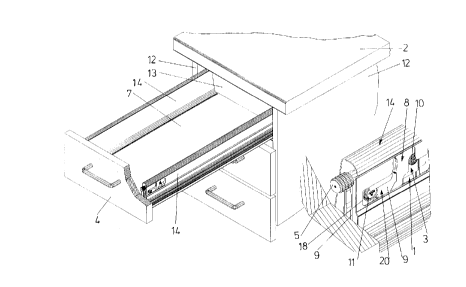
Fig. 1 is a schematic respect view of furniture carcass with a drawer whereby the front
panel thereof is shown cut away in the region of the drawer side wall and the
encircled detail also shown in an enlarged view;
Figs. 2 to 4 show side views of the fastening device according to the invention in
various stages of the suspension of the front panel;

Fig. 5 is a perspective view of the parts of the fastening device before suspension of
15 the front panel;

Fig. 6 is a perspective view of the parts of the fastening device with the holding parts
being held in the support parts;

20 Fig. 7 is a front view of the fastening device and of a front panel;

Fig. 8 is a side view of the fastening device with the front panel being suspended;

Fig. 9 is a perspective view of the fastening device and shows schematically ,ula~ion
25 of the rocker member for unlocking the holding part from the support part;

Fig. 10 shows a side view of the fastening device and schematically rotation of the
rocker member during unlocking;

30 Fig. 11 shows the same side view as Fig. 10, the holding part being fully unlocked and

Fig. 12 shows an exploded respective view of parts of the fastening device and the
drawer side wall.

CA 0221~774 1997-09-17


Fig. 1 shows a fumiture carcass having side walls 12 and a top panel 2 a drawer
being guided in such furniture carcass. On each fumiture side wall a support rail (not
shown) for the drawer is mounted. The front panel 4 of the drawer is secured to the
side walls 14 of the drawer by means of the fastening device 20 according to the5 invention. Each drawer side wall 14 is at its front end provided with a cut-out 18 in the
outer wall which enables a tool to obtain access to the fastening device 20.

At the inner end of the drawer a rear wall 30 is fastened to the drawer side walls 14.

The bottom plate 7 of the drawer rests on lower horizontal webs 17 of profiles 15 (Fig.
7) which are inserted into the drawer side walls 14 and/or on horizontal webs of a pull-
out rail connected to the drawer side wall. Between the support rail of the cabinet and
the pull-out rail of the drawer a center rail for a differential or telescopic pull-out guide
maybe inserted on each side of the drawer.
The drawer side wall 14 which as can be seen especially in Figs. 7 and 12 is
constructed as a doubel-walled frame and covers the rails of the pull-out guide
assembly and the fastening device 20 for securing the front panel 4. With respect to
the function of the fastening device 20 the pull-out rail is part of the drawer side wall
14. The fastening device 20 can be fastened to the drawer side wall 14 as well as to
the pull-out rail.

As best seen in Figs. 5 and 6 the fastening device 20 according to the inventioncomprises a holding part 9 which is fastened to the front panel 4 by means of dowels
5. At the side of the drawer a support part is provided which is mounted on a base
plate 1 which is directly fastened to a profile 15 inserted into the drawer side wall 14
(Fig. 7). The profile 15 can be a profile which extends over the whole length of the
drawer side wall 14 or it can consist of a plurality of profile parts positioned in the
longitudinal direction of the drawer side wall at a distance from each other. The pull-
out rails fastened to the drawer are fastened to the profiles 15 preferably hooked into
this profiles.

The support part 3 is secured in a vertically adjustable manner to the base plate 1 by
means of a clamping screw 10 (Fig. 1) which protrudes through a hole 19 in the

CA 0221~774 1997-09-17


support part 3. In the embodiment the hole 19 is quadrangular. Its size is such that
movement of the support part 3 with respect to the clamping screw 10 is possiblebefore the support part 3 is clamped. An adjustment screw 11 for lateral adjustment of
the front panel 4 is mounted in the holding part 9.


A rocker element 8 which is preferably punched out of sheet steel is mounted in the
support part 3 as shown in nearly all of the figures. The rocker element 8 is provided
with a shank 21 which protrudes through a slot 22 in a flap 23 of the support part 3.
The spring 6 which is a pressure spring and a helical spring is mounted on the shank
21 the spring abutting the support part 3 for example on the flap 23 on the one side
and the rocker element 8 for example on lateral stops 24 of the shank 21 on the other
side.

The rocker element 8 is at its front ends provided with two hooks 25, 26 directed
towards each other and a lower stop 27. Further the rocker element 8 is provided with
a hole 28 which permits insertion of a screw driver 16 (Fig. 9, 10). The support part 3
as can be seen especially in Figs. 8, 9 and 12 is provided with a case-like area at its
front which is provided with an upper horizontal web 30, a lower horizontal web 29
and a vertical border web 31 extending in an angle from the upper horizontal web 30.
The upper horizontal web 30 is provided with a slot 32 in which, as can be seen in Fig.
5, the hook 25 of the rocker element 8 protrudes when the holding part 9 is released
from the support part 3. The lower horizontal web 29 is provided with a slot 33 opened
to the rear into which the rocker element 8 protrudes with its lower amm 34 on which
the hook 26 and the stop 27 are formed. Further, the support part 3 is on its mounting
plate 35 provided with a slot 36 which is bordered by a rack profile 37 at its upper rim.

The rack profile 37 and the slot 36 are at their front end provided with a curved portion
38.

30 Before mounting the front panel 4 on the drawer side walls 14 the holding parts 9 are
fastened to the front panel 4 by means of dowels 5 and the supporting parts 3 with
the rocker elements 8 are screwed to the base plate 1 by means of the screw 10 and
therefore fastened within the drawer side wall 14.

CA 0221~774 1997-09-17


At this stage the rocker member 8 is in the position shown in Fig. 2. If the holding
member 9 is pushed into the case-like area of the support part in the direction of the
arrows of Figs. 2 and 3 whereby it is guided between the horizontal webs 29, 30 it
abuts with an edge 39 an inclined plane 40 of the hook 25 and pushes the rocker
5 member 8 in the direction shown by the arrows of Fig. 3 upwardly and moves therocker member 8 clockwise. Because of this the lower hook 26 of the rocker member
8 engages behind the web 41 of the holding part 9 and the holding part 9 is secured
in the support part 3 as shown in Fig. 4. The rocker member 8 and consequently the
holding part 9 with the front panel 4 are now pulled to the rear by the spring 6 and
10 therefore the front panel 4 is pressed onto the front end planes of the drawer side
walls 14.

If the drawer is pushed into the fumiture carcass with excessive vigour and the front
panel 4 abuts against the front end edges of the fumiture side walls 12 the support
15 part 3 together with the drawer side walls 14 can move a small distance away from the
holding part 9 so that the drawer is so to say detached from the front panel andmoves further into the furniture carcass. Once the push-in energy is expended the
drawer side walls 14 are pushed against the front panel 4 by the springs 6.

20 In order that the front panel 4 does not stress the spring 6 excessively when the
drawer is pulled out a stop 27 is provided on the rocker element 8 which when the
rocker element 8 reaches its front-most position abuts the horizontal web 29 of the
support part at the end of the slot 33.

25 If the front panel 4 is to be detached from the drawer side walls a screw driver 16 is
inserted into the hole 28 of the rocker element 8 as shown in Figs. 9 and 10 so that
the front end of the screw driver 16 meshes with the rack profile 37 in the support part
3. If the screw driver 16 is rotated counter-clockwise the rocker element 8 is tilted
whereby its hook 25 engages in the slot 32 of the upper horizontal web 30 of the30 support part and the hook 26 is pushed downwardly away from the web 41 of theholding part 9 and the holding part 9 is released. The holding part 9 can now be pulled
out of its hold in the support part 3.

CA 0221~774 1997-09-17


For optimal utilisation of the strength of the spring 6 the shaft 21 is bent,
advantageously provided with a knee so that the free end of the shaft 21 with the
stops 24 is directed slightly downwardly as shown in Fig. 8 when the holding part is
engaged.


Stability of the fastening device 20 is improved by the rocker member 8 being held in
the slot 33 and in the realised position with its hook 25 in the slot 32 of the support
part3.


Dessin représentatif
Une figure unique qui représente un dessin illustrant l'invention.
États administratifs

Pour une meilleure compréhension de l'état de la demande ou brevet qui figure sur cette page, la rubrique Mise en garde , et les descriptions de Brevet , États administratifs , Taxes périodiques et Historique des paiements devraient être consultées.

États administratifs

Titre Date
Date de délivrance prévu Non disponible
(86) Date de dépôt PCT 1996-03-14
(87) Date de publication PCT 1996-09-26
(85) Entrée nationale 1997-09-17
Demande morte 2003-03-14

Historique d'abandonnement

Date d'abandonnement Raison Reinstatement Date
2002-03-14 Taxe périodique sur la demande impayée

Historique des paiements

Type de taxes Anniversaire Échéance Montant payé Date payée
Enregistrement de documents 100,00 $ 1997-09-17
Le dépôt d'une demande de brevet 300,00 $ 1997-09-17
Taxe de maintien en état - Demande - nouvelle loi 2 1998-03-16 100,00 $ 1998-03-12
Taxe de maintien en état - Demande - nouvelle loi 3 1999-03-15 100,00 $ 1999-03-03
Taxe de maintien en état - Demande - nouvelle loi 4 2000-03-14 100,00 $ 2000-02-28
Taxe de maintien en état - Demande - nouvelle loi 5 2001-03-14 150,00 $ 2001-03-07
Titulaires au dossier

Les titulaires actuels et antérieures au dossier sont affichés en ordre alphabétique.

Titulaires actuels au dossier
JULIUS BLUM GESELLSCHAFT M.B.H.
Titulaires antérieures au dossier
BRUSTLE, KLAUS
Les propriétaires antérieurs qui ne figurent pas dans la liste des « Propriétaires au dossier » apparaîtront dans d'autres documents au dossier.
Documents

Pour visionner les fichiers sélectionnés, entrer le code reCAPTCHA :


Pour visualiser une image, cliquer sur un lien dans la colonne description du document. Pour télécharger l'image (les images), cliquer l'une ou plusieurs cases à cocher dans la première colonne et ensuite cliquer sur le bouton "Télécharger sélection en format PDF (archive Zip)" ou le bouton "Télécharger sélection (en un fichier PDF fusionné)".

Liste des documents de brevet publiés et non publiés sur la BDBC .

Si vous avez des difficultés à accéder au contenu, veuillez communiquer avec le Centre de services à la clientèle au 1-866-997-1936, ou envoyer un courriel au Centre de service à la clientèle de l'OPIC.


Description du
Document 
Date
(yyyy-mm-dd) 
Nombre de pages   Taille de l'image (Ko) 
Abrégé 1997-09-17 1 28
Page couverture 1997-12-19 2 93
Dessins représentatifs 1997-12-19 1 30
Description 1997-09-17 7 277
Revendications 1997-09-17 2 88
Dessins 1997-09-17 6 189
Cession 1997-09-17 2 97
Correspondance 1997-11-28 1 27
PCT 1997-11-26 6 156
Correspondance 1998-01-29 1 25
Cession 1998-01-29 2 53
Rapport d'examen préliminaire international 1997-09-17 14 480