Note : Les descriptions sont présentées dans la langue officielle dans laquelle elles ont été soumises.
CA 02347220 2001-04-18
1
FILLETING DEVICE
The invention relates to a device and a method for
removing the fillets from the eviscerated carcasses of
poultry whose extremities have been detached.
From EP A1 168 865 is known a device of this kind
which is designed to remove the head portion of the
wishbone (clavicula), wherein this operation is however
before a filleting process whose result is a double
fillet including the breast meat in the form of outer and
inner fillets. With this device, the poultry carcasses
present as front halves are mounted on the saddles of a
rotationally driven conveyor, so that the saddle horn
extends into the neck opening and the breast portion
faces upwards. Filleting of the poultry carcass being
conveyed with the neck opening in front is effected on
the lower run of the device and begins with retention of
the breast meat and hence stripping thereof from the
wishbone to the breastbone (sternum) and is continued by
a scraping tool which is adapted to the shape of the
poultry carcass and, by penetration between skeleton and
meat, causes separation of the meat up to the keel of the
breastbone (crista sterni). By means of scraping fingers
which then follow, detachment from the flanks of the
breastbone is effected in its region of transition to the
breastbone plate (corpus sterni) and finally complete
separation of the double fillet by means of rotationally
driven peeling belts. A further practical example of this
state of the art provides as the first filleting tool a
pair of milling rollers which lift the fillet meat
located in the region of the ribs off the skeleton.
Behind this tool is a scraping tool after the fashion of
the one described above, which causes separation of the
meat up to the keel of the breastbone. Complete
separation of the double fillet is finally again
undertaken by a tool consisting of rotationally driven
peeling belts.
Amended sheet
CA 02347220 2005-02-25
2
From EP-A1 207 5S3 is known a further device far
recovery of the meat from poultry carcasses in the form
of double fillets. Here too the starting product is the
front half of a poultry carcass which is inverted over
the saddle horn of a saddle which forms part of a
revolving conveyor. an inversion, the wing joints and
hence the points of application of the wishbone are kept
forced inwards, and the poultry carcass is thus supplied
to the filleting tools which are arranged along the lower
run of the conveyor and recover the fillet meat
essentially by pushing it off.
A further device and a method for the mechanical
recovery of meat from poultry carcasses can be found in
document EP 591 741. The device shown there for removal
of the fillets includes several processing tools. The
processing tools constructed as scraping devices are
connected to a control mechanism by which the scraping
elements are controlled, wherein control or activation of
the tools is effected in each case as a function of the
size of the products to be processed.
All known devices or methods for the recovery of
fillets have the drawbacl~ that, due to the different
geometries of the naturally grown carcasses, it is
frequently not possible to obtain an optimum of fillet
meat at the same time as a visually pleasing product.
It is now the object of the present invention to
increase the yield of fillet meat, at the same time with
a visually pleasing product.
According to the present invention, there is provided a device for
removing fillets from eviscerated carcasses of poultry whose extremities have
been detached, including at least one measuring device for measuring
individual
carcass dimensions, at least one control unit and at least one scraping
device,
characterised in that the measuring device is connected via the control unit
to the
at least one scraping device for the purpose of communicating, wherein the
CA 02347220 2005-02-25
3
measuring device is for detecting body joint points and the at least one
scraping
device is constructed as a disc-like scraping element. This ensures that
firstly
exact data on the individual carcass dimensions can be determined, so that an
increased yield can be obtained, as the points of application or engagement of
the
scraping device can be determined precisely. Secondly the disc-like
construction
of the or each scraping device ensures careful penetration between skeleton
and
meat, so that injuries, particularly to the bones, can be effectively avoided.
Thus
the quality of the fillet meat obtained is improved, because for example bone
residues in the fillet are prevented.
In a preferable development of the invention, the or each scraping
elements is of rotatable construction. Due to the rotating scraping elements,
initial
detachment or cutting is made easier, with the result that on the one hand an
improvement in quality and on the other hand an increase in yield is obtained.
Preferably, according to the invention it is provided that at least one
scraping device comprises an element for pulling back the tender sinew. This
increases the reliability of initial cutting still further and leads to
fillets free from
damage.
Further it may be provided according to the
invention that the or each scraping device comprises at
least two disc-like scraping elements.
Preferably the disc-like scraping elements are of
pivotable construction sack that the circumferential
surfaces of their discs are arranged so that they can be
rolled over the wishbone from the body joint of the
poultry .carcass. This construction ensures that clean
separation of the fillet meat from the skeleton is
carried out, so that the yield is further increased.
Preferably, according to the invention, there is provided that in front of
each scraping device in the direction of conveying is arranged at least one
measuring device.
CA 02347220 2005-02-25
4
According to the present invention, there is also provided a method for
removing fillets from eviscerated carcasses of poultry whose extremities have
been detached, including the steps of:
- introducing the carcasses of poultry into the device;
- detection of the individual carcass dimensions by recording carcass-specific
data,
- control of the at least one scraping device and mounting of the at least one
scraping element on previously determined body aoint points,
- subsequent detachment of the fillets from the skeleton by the at least one
disc-like scraping element, and
final and complete detachment of the fillets by subsequent scraping tools.
By this method according to the invention, exact
separation of the meat from the skeleton with maximum
yield is possible. Furthermore, the method according to
the invention ensures very careful separation of the
fillets from the skeleton so that damage, due to which
for example bone residues remain in the fillet, can be
prevented.
A practical example of the device according to the
invention is described in more detail with the aid of the
drawings. They show;
Figure 1 a stripped view of the poultry carcass
Figure 2 a simplified side view of a poultry carcass on
a saddle with activated clamping lever
Figure 3 a side view of a detail of a poultry processing
device
Figure 4 a top view according to Figure 3.
In Figure 1 is shown part of a poultry carcass 1
with reference to its bone structure which essentially
consists of a breastbone 2, from which the coracoid bones
3 extend forwards, or in the direction of conveying 29.
CA 02347220 2001-04-18
The wishbone 4, which extends as far as the wishbone head
5, is connected by the body joints 6 to the coracoid
bones 3. This poultry carcass 1 is mounted on a saddle 9
which is in turn fixed in a frame, not shown in more
detail, of a device for recovery of the breast meat from
slaughtered poultry on an endlessly rotating conveyor 26.
The part of the poultry carcass 1 which is shown in
Figure 1 is produced by an oblique cut transversely
through the poultry carcass 1, wherein the cut is made
while separating the pelvis with the legs and while
cutting through the vertebral column roughly parallel to
the ribs connected to the vertebral column.
In Figure 2 is shown a poultry carcass 1 on a saddle
9 in a side view, the poultry carcass 1 being pressed
against the saddle 9 by means of the activated clamping
lever 8. The inner contour of the breastbone plate 10
rests on the saddle 9. Essentially the poultry carcass 1
consists of the breastbone 2, from which the coracoid
bones 3 extend in the direction of the body joints 6. The
wishbone 4, which extends as far as the wishbone head 5,
is connected to the coracoid bones 3 by the body joints 6
to which are also attached the scapulae 7. The poultry
carcass 1 is mounted on a saddle 9 which is fixed in a
CA 02347220 2001-04-18
6
frame, not shown in more detail, of a device for recovery
of the breast meat from slaughtered poultry on an
endlessly rotating conveyor 26.
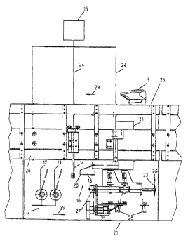
In the view according to Figure 3 can be seen a side
view of a poultry processing device, as can be seen for
example in EP 168 865, particularly in Figure 1 there.
The poultry carcass, not shown, which as described
in Figures 1 and 2 is located on the saddles 9 arranged
at regular intervals on the endlessly rotating conveyor
26, passes with its breastbone plate facing downwards
into the input region of the measuring device 11.
This is because the arrangement of the device for
removing the fillets selected in the embodiment shown is
mounted below the endlessly rotating conveyor 26. In this
way the ultimately removed fillet drops, assisted by
gravity, into a collecting vessel suitably arranged below
the device. In the region of the measuring device 11 the
poultry carcass which is moved by means of conveyor 26
must successively pass in the direction of conveying 29
through a first measuring element 12 and a second
measuring element 13, wherein the measuring element 12 is
important for detection of one body joint, and the
measuring element 13 is important for detection of the
other body joint. As can be seen from Figure 1, the body
joints 6 are arranged essentially parallel and adjacent
to each other in one plane, so that it follows that the
measuring elements 12 and 13 are mounted with offset
tracks according to the distance between the body joints
6. After the measuring elements 12 and 13, the poultry
carcass passes through a third measuring element 14 which
consists of two elements. These two elements are arranged
in one plane and resemble double swing doors. The signals
obtained individually from the measuring elements just
described in relation to the respective dimensions of the
poultry carcasses are transmitted directly to a control
unit 15 by means of the signal wires 24 and serve
CA 02347220 2001-04-18
7
essentially for individual identification of the position
of the body joints of each individual poultry carcass
which passes by means of conveyor 26 into the region of
the device for recovery of the fillet. But it is also
possible with the device shown to make statements
regarding the height, width and length of the poultry
carcass. The control unit 15 now signals the arrival of
each poultry carcass, but in particular the position of
the body joints 6 of the respective poultry carcass, to
the first scraping device 16. This scraping device 16
consists of a left scraping element 17 and a right
scraping element 18, wherein these scraping elements 17,
18 arranged adjacent to each other essentially simulate
the contour of the poultry carcass from the viewpoint of
the approaching poultry carcass. The scraping elements
17, 18 are arranged pivotably relative to each other, so
that they can be spaced apart e.g. by means of a signal
from the control unit 15 in relation to the individual
width of the poultry carcass. The left scraping element
17 has a left sinew restraint device 19 which is intended
to find and restrain the tender sinew located in the
region of the body joint, so that the scraping element
can pass unhindered into the region between bone and meat
and so obtain an optimum yield. The right scraping
element 18 has a right sinew restraint device 20 which is
intended to find the corresponding tender sinew located
on the opposite body joint. After the first scraping
device is located a second scraping device 21 which,
arranged essentially symmetrically to the direction of
conveying, comprises a left disc 22 and a right disc 23
which are preferably made of metal, wherein these discs
22, 23 can be driven with a disc drive 27. These discs
22, 23 are slidable by means of disc pivot levers 28 in
such a way that, the moment the control unit 15 indicates
via the signal wires 24 the appearance of the body joints
6 of the poultry carcass within range of the second
CA 02347220 2005-02-25
8
scraping device, the circumferential surface 25 of the
discs 22, 23 moves towards the corresponding body joint
and abuts against it. In the course of the movement of
the poultry carcass caused by the conveyor 26 the discs
22, 23 move on the corresponding part of the symmetrical
wishbone 4 towards i.ts wishbone head 5 in order to detach
the meat connected to the wishbone 4. After reaching the
wishbone head, the .rotating discs 22, 23 are steered out
of direct range of the poultry carcass. In a special
embodiment the discs 22, 23 are blunt, particularly in
the region of their circumferential surface 25.
In a further alternative embodiment it is provided
that in the region between first scraping device 16 and
second scraping device 21 is arranged a further measuring
device 11 for checking the carcass coordinates, which may
possibly have changed after a processing operation.
In another alternative embodiment it is provided
that the scraping devices 16, 21 already described above
are arranged in the reverse order, so that the poultry
carcass passes through first the scraping device 2,1 and
then the scraping device 16, wherein here too the
additional alternative that a further measuring device is
arranged between the scraping devices 21, 16 is
conceivable.
In the view according to Figure 4 can be seen a side
view and a top view of a poultry processing device
according to Figure 3. In the region of the measuring
device 11, the poultry carcass which is moved with the
conveyor 26 shown in Figure 3 must pass successively in
the direction of conveying 29 through a first measuring
element 12 and a second measuring element 13, wherein the
measuring element 12 is important for detection of one
body joint 6, and the measuring element 13 is important
for detection of the other body joint 6, which are shown
in Figure 1. As can be seen from Figure 1, the body
joints 6 are arranged essentially parallel and adjacent
CA 02347220 2001-04-18
9
to each other in one plane, so that it follows that the
measuring elements 12 and 13 are mounted with offset
tracks according to the distance between the body joints
6, which can be seen in particular in Figure 4 II. After
the measuring elements 12 and 13, the poultry carcass
passes through a third measuring element 14 which
consists of two elements, the left element 30 and the
right element 31. These two elements are arranged in one
plane and resemble double swing doors. The signals
obtained individually from the measuring elements just
described in relation to the respective dimensions of the
poultry carcasses are transmitted directly to a control
unit 15 by means of the signal wires 24 shown in Figure 3
and serve essentially for individual identification of
the position of the body joints as well as the volume and
external dimensions of each individual poultry carcass
which passes by means of conveyor 26 into the region of
the device for recovery of the fillet. The control unit
which can also be seen in Figure 3 now indicates the
arrival of each poultry carcass, but in particular the
position of the body joints 6 of the respective poultry
carcass, to the first scraping device 16: This scraping
device 16 consists of a left scraping element 17 and a
right scraping element 18. The scraping elements 17, 18
are arranged pivotably relative to each other, so that
they can be spaced apart e.g. by means of a signal from
the control unit 15 in relation to the individual width
of the poultry carcass. The left scraping element 17 has
a left sinew restraint device 19 which is intended to
find and restrain the tender sinew located in the region
of the body joint, so that the scraping element can pass
unhindered into the region between bone and meat and so
obtain an optimum yield. The right scraping element 18
has a right sinew restraint device 20 which is intended
to find the corresponding tender sinew located on the
opposite body joint. After the first scraping device is
CA 02347220 2005-02-25
located a second scraping device 21 which, arranged
essentially symmetrically to the direction of conveying,
comprises a left disc 22 and a right disc 23, wherein
these discs 22, 23 can be driven with a disc drive 27
which can be driven with a drive belt, not shown in more
detail, by a motor, also not shown. These discs 22, 23
are slidable by means of disc pivot levers 28 in such a
way that, the moment the control unit 15 indicates via
the signal wires 24 the appearance of the body joints 6
10 of the poultry carcass within range of the second
scraping device, the circumferential surface 25 of the
discs 22, 23 moves towards the corresponding body joint
and abuts against it. In the course of the movement of
the poultry carcass caused by the conveyor 26. the discs
22, 23 move on the corresponding part of the symmetrical
wishbone 4 towards its wishbone head 5 in order to detach
the meat connected to the .wishbone 4. After reaching the
wishbone head, the rotating discs 22, 23 are again
steered out of direct range of the poultry carcass. In a
special embodiment the discs 22, 23 are blunt,
particularly in the region of their circumferential
surface 25.
In another alternative embodiment according to
Figure 4 III it is provided that the scraping devices 15,
21 already described above are arranged in the reverse
order, so that the poultry carcass passes through first
t:ne scraping device 21 and then the scraping device 16,
wherein here too the additional alternative that a
further measuring device is arranged between the scraping
devices 21 and 16 is conceivable. In a further
alternative embodiment it is provided that the measuring
device 11 has a photoop~ical element, e.g. a camera which
in conjunction with a processor unit and a mathematical
process, such as for example triangulation, determines
volume and carcass data, or its coordinates, e.g. the
wishbone shave.
CA 02347220 2005-02-25
11
~15t Of reference numbers
1 poultry carcass
2 breastbone
3 coracoid bone
4 wishbone
wishbone head
6 body joint
7 shoulder blades
8 clamping lever
9 saddle
10 breastbone plate
11 measuring device
12 first measuring element
13 second measuring element
14 third measuring element
control unit
16 first scraping device
17 left scraping element
18 right scraping element
19 left sinew restraint device
20 right sinew restraint device .
21 second scraping device
22 left disc
23 right disc
24 signal wire
disc circumferen-tial surface
26 conveyor
27 disc drive
28 disc pivot lever
~0 29 direction of conveying
left element
31 right element