Note : Les descriptions sont présentées dans la langue officielle dans laquelle elles ont été soumises.
CA 02417068 2003-O1-22
TITLE: SHOWER BATH TAF' VALUE ASSEMB~I;Y
BACKGROUND OF THE INVENTION
(a) Field of the Invention
The present invention is related to a shower bath tap valve assembly,
and more particularly, to one that is firmly secured in balance, allows easier
production and assembly, and can be adapted to a ceramic or a general
cartridge.
(b) Description of the Prior Art:
A shower bath tap in the present invention relates to a fixed tap in
configuration as illustrated in Fig. 1 of the accompanying drawings.
Wherein, a valve assembly 1 is mounted to a disk shape base 2; a handle 3
provided on the base 2 connects a cartridge of the valve assembly to control
water amount delivered; a cold water inlet 1 l, a hot; water inlet 12, a water
outlet 13, a drain 14, a trough 15 to accommodate the cartridge, and another
trough 16 to accommodate a balance valve are pro'~ided on the valve body;
the water outlet 13 is connected to a diverter (not il~~ustrated); and the
valve
assembly 1 is then provided with the pipe work to connect through a shower
head 4 and a bathtub tap 5.
The shower bath tap as described above is characterized by that both
cold and hot water before entering into a valve body 10 pass through a balance
CA 02417068 2003-O1-22
valve 20 and a cartridge 30 where both cold and hot water are properly mixed
and deliver through the water outlet 13. Both of the cartridge 30 and the
balance valve 20 are members of the prior art in their configuration as
illustrated in Figs. 3, 5, and 6. The operation of th.e balance valve 20 is
illustrated in Fig. 7, wherein, both of cold and hot water from the water
supply
lines flow respectively through the cold and hot water tubes 11, 12 of the
valve
body 10 into the balance valve 20. As illustrated i:n Fig. 7A, a mobile part
22
of the balance valve 20 remains staying at the center for being subject to the
equal pressure from the cold water and the hot water if the amount delivered
of both cold and hot water are equal for both of cold and hot water to flow to
the balance valve 20 through a left water way 221 and a right water way 222.
As illustrated in Fig. 7B, when only cold water is supplied through the cold
water inlet 11, water current pressure is applied through the left water way
221
of the mobile part 22 on a separation plate 223 to rr~ove the mobile part 22
to
its right, thus to block a left water pore 211 of a fixed part 21 to prevent
the
cold water from being delivered. On the contrary, if only hot water is
supplied through the cold water inlet 12 as illustrated in Fig. 7C, water
current
pressure is applied, the mobile part 22 is moved to its left to block a right
water
pore 212 of a fixed part 21 to prevent the hot water from being delivered.
Referring to Fig. 6, both cold and hot water flowing through the balance valve
CA 02417068 2003-O1-22
enters into the cartridge 30 are mixed in the cartridge 30 and the mixing
ratio
is controlled by turning the handle 3 before allowing the mixed water to be
delivered through the water outlet 13. This type of shower bath tap is known
for its advantage of given a very accurate regulation and control of the
temperature of the water delivered through the balance valve and the
cartridge.
However, the mechanism of the cartridge may be ovf a general one or a
precision ceramic one, and the configuration of the balance valve varies
depending on which one is used. Accordingly, various types of valve body
must be designed to cope with the cartridge and the balance valve for
assembly, resulting in higher production and assembly costs due to
inconsistent structures among the members.
CA 02417068 2003-O1-22
SUUMMARY OF INVENTION
The primary purpose of the present invention is to provide a shower
bath tap assembly housing a cylindrical balance valve seat to accommodate a
balance valve that can be directly placed in a central trough of the valve
body
and adapted to a general or a ceramic cartridge in achieving the standardized
specification for the tap valve assembly for production and assembly costs
reduction.
The foregoing obj ect and summary provide only a brief introduction to
the present invention. To fully appreciate these and other objects of the
present invention as well as the invention itself, all of which will become
apparent to those skilled in the art, the following detailed description of
the
invention and the claims should be read in conjunction with the accompanying
drawings. Throughout the specification and drawings identical reference
numerals refer to identical or similar parts.
Many other advantages and features of the present invention will
become manifest to those versed in the art upon making reference to the
detailed description and the accompanying sheets of drawings in which a
preferred structural embodiment incorporating the principles of the present
invention is shown by way of illustrative example.
CA 02417068 2003-O1-22
BRIEF DESCRIPTI~N ~F THE DRAWIhIGS
Fig. l is an exploded view of the prior art of tlZe present invention.
Fig. 2 is a view showing an assembly of a preferred embodiment of the
present mventlon.
5 Fig. 3 is an exploded view of the preferred embodiment of the present
invention.
Fig. 4 is a top view of the preferred embodiment of the present
invention.
Fig. 5 is a sectional view of the preferred embodiment of the present
invention.
Fig. 6 is another sectional view of the preferred embodiment of the
present lnventlon.
Fig. 7 is a schematic view showing the operation of a balance valve in
the preferred embodiment of the present invention.
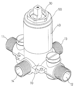
Fig. 8 is a view showing the appearance of tree preferred embodiment of
the present invention.
Fig. 9 is an exploded view of the preferred embodiment of the present
invention.
CA 02417068 2003-O1-22
DETAILED DESCRIPTION OF THE PREFERRED EMBODIMEI~1T
The following descriptions are of exernplarrr embodiments only, and
are not intended to limit the scope, applicability or configuration of the
invention in any way Rather, the following description provides a
convenient illustration for implementing exemplary embodiments of the
invention. Various changes to the described embodiments may be made in
the function and arrangement of the elements described without departing
from the scope of the invention as set forth in the appended claims.
Referring to Figs. 2 through 6, a preferred embodiment of the present
invention is comprised of a val~~e body 10, a balance valve 20; a ceramic
cartridge 30, a sleeve 40, a fixation nut 50 and a balance valve seat 60.
Wherein, the valve body 10 is provided with a cold water inlet 11, a hot water
inlet 12, a water outlet 13 and a drain 14 all connecvted through a central
trough
of the valve body 10. The balance valve 60 in its outer diameter same as
1 ~ to that of a cylinder provided in the bore of the central trough is
directly placed
in the central trough 15. An accommodate trough. 61 is provided on one side
of the cylinder to receive the balance valve (a memlber of the prior art)
comprised of a fixed part 2 l and a mobile part 22; a cold water way 62, a hot
water way 63 and a water outlet way 64 are providf;d on the end surface of the
cylinder with both of the cold and hot water ways 62, 63 being connected
CA 02417068 2003-O1-22
through the accommodation trough 61. The ceramic cartridge 30, also a
member of the prior art, is provided at its bottom a cold water inlet, a hot
water
inlet and a water outlet and contains a current mixing mechanism; and a rod
extending from its top being connected to the handle 3 to directly have the
ceramic cartridge 30 mounted on the balance valve seat, covered with the
sleeve 40 and secured in the central trough I 5 of the valve 10. Furthermore,
the fixation nut 50 is screwed to the central trough I 5 of the valve body 10
before being screwed to the other end ofthe sleeve to complete the assembly
of the entire valve body Wherein, both of the cold and hot water ways 62,
63 of the balance valve seat 60 are respectively connected at their lower ends
through both of the cold and hot water inlets 1 l, 12 of the valve body while
their lower ends are respectively connected to cold .and hot water inlets of
the
ceramic cartridge 30. The water outlet way 64 of the balance valve 60 is
connected at its top to the water outlet of the ceramic cartridge 30 and its
lower
end, to the water outlet I 3 of the valve body 10 so tlhat both of the cold
and hot
water outlet entering into their respective water inlets 1 l, I2 have to first
flow
through the balance valve seat 60 to undergo regulation and control of closing
or opening the water ways at the balance valve 20 (:in a way in consistency to
the prior art) before entering into t<he ceramic cartridge 30 where both cold
and
hot water are mixed at a proper ratio by fuming the :handle 3 and delivered
CA 02417068 2003-O1-22
from the water outlet 1 ~ of the valve body through the water outlet way 64 of
the balance valve seat. Furthermore, as illustrated in Figs. 8 and 9, the
specification of the valve body 10 can be standardi~~.ed due to the
installation
of the balance valve seat 60 of the present invention, thus is also applicable
for
the assembly with a general cartridge.
It will be understood that each of the elements described above, or two
or more together may also find a useful application in other types of methods
differing from the type described above.
While certain novel features of this invention have been shown and
described and are pointed out in the annexed claim, it is not intended to be
limited to the details above, since it will be understood that various
omissions,
modifications, substitutions and changes in the forms and details of the
device
illustrated and in its operation can be made by those; skilled in the art
without
departing in any way from the spirit of the present invention.