Sélection de la langue

Search

Sommaire du brevet 2564519 

Énoncé de désistement de responsabilité concernant l'information provenant de tiers

Une partie des informations de ce site Web a été fournie par des sources externes. Le gouvernement du Canada n'assume aucune responsabilité concernant la précision, l'actualité ou la fiabilité des informations fournies par les sources externes. Les utilisateurs qui désirent employer cette information devraient consulter directement la source des informations. Le contenu fourni par les sources externes n'est pas assujetti aux exigences sur les langues officielles, la protection des renseignements personnels et l'accessibilité.

Disponibilité de l'Abrégé et des Revendications

L'apparition de différences dans le texte et l'image des Revendications et de l'Abrégé dépend du moment auquel le document est publié. Les textes des Revendications et de l'Abrégé sont affichés :

  • lorsque la demande peut être examinée par le public;
  • lorsque le brevet est émis (délivrance).
(12) Brevet: (11) CA 2564519
(54) Titre français: PROFIL RENFORCE ET RAINURE
(54) Titre anglais: GROOVED STIFFENED PROFILE
Statut: Réputé périmé
Données bibliographiques
Abrégés

Abrégé français

Un nouveau profil strié rigidifié dont les caractéristiques mécaniques sont supérieures à celles des profils structuraux connus. Ce nouveau profil peut être utilisé tant pour la construction de renforts de toitures ou de voûtes architecturales de grande dimension, supportant efficacement les charges mortes. Ce profil est constitué d'une âme, de côtés se trouvant sur la partie supérieure et inférieure et de terminaisons recourbées formées sur les extrémités de la pièce où les côtés sont constitués d'une surface plane divisée en trois parties ou sections: une première section de surface plane, assemblée sur une extrémité à l'âme au moyen d'un fléchissement formant 90 degrés et, sur l'autre extrémité, présentant un fléchissement sur une section intermédiaire de surface plane, déplacée de l'axe central des côtés et formant la section en retrait. On prévoit un second fléchissement sur la troisième section de surface plane laquelle reste sur le même plan que la première section suivie d'un fléchissement avec un des terminaisons recourbées de manière à ce qu'ils soient à 90 degrés par rapport aux côtés. L'âme, ayant une surface plane, est formée de trois sections: une première section plane, assemblée sur l'extrémité supérieure au fléchissement du côté supérieur, lequel formera un angle de 90 degrés afin de se prolonger en section médiane à surface plane déplacée par rapport à l'axe de l'âme et formant la section en retrait. Cette dernière est assemblée au moyen de fléchissements et est suivie d'une troisième section semblable à la première ayant une surface plane, laquelle se trouve sur le même plan que la première section et se termine avec un second fléchissement sur le côté inférieur qui formera un angle de 90 degrés par rapport à l'âme. Ainsi, l'invention trouve une application dans le monde des profils structuraux utilisés pour la construction de renforts.


Abrégé anglais


A shaped metal beam is described, having a generally
C-shaped profile which includes a central part, opposed
sidewalls extending along the lateral sides of the central
part, and opposed flanges extending from the sidewalls
comprising inwardly-turned walls opposed to and parallel to
the central part. The central part, sidewalls and flanges
define a hollow interior open to one side. The central part
and the sidewalls each comprise first and second flat outer
sections adjacent to the lateral sides thereof, the flat outer
sections being co-planar, and a third section intermediate
between the lateral sides. The third section comprises a
central channel recessed towards the interior of the beam
having a flat floor and non-parallel, converging channel
sidewalls. The width of the respect outer sections and
channel may all be substantially equal within each of the
central part and sidewalls.

Revendications

Note : Les revendications sont présentées dans la langue officielle dans laquelle elles ont été soumises.


6
CLAIMS:
1. A formed metal beam having a generally C-shaped profile
comprising a central part, opposed sidewalls extending along
the lateral sides of said central part, and opposed flanges
extending from said sidewalls comprising inwardly-turned walls
opposed to and parallel to said central part, said central
part, sidewalls and flanges defining a hollow interior open to
one side, said central part and said sidewalls each
comprising first and second flat outer sections adjacent to
the lateral sides thereof, said flat outer sections being co-
planar, and a third section intermediate between said lateral
sides, said third section comprising a central channel
recessed towards the interior of said beam having a flat floor
and non-parallel, converging channel sidewalls.
2. The beam of claim 1 comprising smoothly curved bends of
90 degrees where said central part joins with said sidewalls
and said sidewalls join with said flanges.
3. The beam of claim 1 wherein the transverse width of the
outer sections of the central part and the transverse width of
the floor of the channel of said central part are
substantially equal.
4. The beam of claim 1 wherein the transverse width of the
outer sections of the sidewalls and the transverse width of
the floor of the channel of said sidewalls are substantially
equal.
5. A method of forming the beam of any one of claims 1-4,
comprising the steps of providing a flat metal blank, and
forming said beam by shaping the blank with a rolling machine
or shaping machine in a plurality of rolling or shaping
operations.

Description

Note : Les descriptions sont présentées dans la langue officielle dans laquelle elles ont été soumises.

CA 02564519 2006-10-23
GROOVED STIFFENED PROFILE
SCOPE OF THE INVENTION
This is a new grooved stiffened profile with
mechanical characteristics superior to already known
structural profiles, that can be used in building
frameworks for roofing or large architectural vaults, that
efficiently supports dead weight.
The qualities of its maximum work stress notoriously
compete with conventional profiles because of the
stiffeners included in it. Additionally, the weight per
lineal meter is less than the first, which makes this
invention a versatile profile for building roof frameworks
and wide vaults.
Therefore, the scope of the invention is subscribed to
the universe of structural profiles used in building
frames.
HISTORY OF THE INVENTION
In Mexico, as well as in other countries, roofs are
built on constructions that have no intermediary supports,
and outside walls or columns that are separated more than
10 m (40 feet); therefore, and for economic reasons,
builders resort to the use of a structural system other
than simply supported beams. The structural configuration
used for this purpose is called a roof framework; a
framework is a structural configuration of elements

CA 02564519 2006-10-23
2
normally supported at the ends and formed by a series of
elements, normally straight, laid out in a certain order
and connected one to another, in such manner that stress
transmitted from one element to another is the same or is
uniformly distributed. As a triangle is the only polygon
with a form that can be geometrically modified without
changing the length of one or more of its sides, the
framework essentially consists of a system of triangles.
In steel frameworks it is common practice that angles
be connected among themselves by a connecting plate and
rivets, screws and nuts, or welding, forming rigid
connections; the stability of a framework does not depend
on the rigidity of its joints.
We know that steel profiles have been greatly
substituting other elements such as wood, mainly because
longer open spaces can be built with steel.
Steel structural profiles most frequently used in the
construction of buildings are beams with (WF) wide flanges;
standard I beams, grooved sections, angles and plates.
After numerous investigations, a profile has been
developed with the technical and mechanical characteristics
of the conventional profiles described, but featured for
being stiffened, which provides it more rigidity, and
appears as an element that supports more loads, and
therefore, the same stress as a conventional profile

CA 02.51519 2006-10-23
3
support; with the use of the profile being proposed; this
profile supports more stress, which permits us to reduce
weight and build structures with wider open spaces.
BRIEF DESCRIPTION OF DRAWINGS
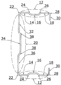
FIG. 1 is a sectional view of the stiffened profile;
FIG. 2 is a perspective of the stiffened profile.
DESCRIPTION OF THE INVENTION
Referring to the drawings described above, the
stiffened profile of this invention is formed by a machined
part (10) in a grooved form, that fundamentally includes a
central part (20), some flanges (12) located in the upper
and lower parts and some finished ends (30), placed at the
ends of the machined part (10).
These flanges (12) or sides consist of a flat surface,
divided into three parts or sections: a first section (14)
with a flat surface, joined at one end to the central part
(20) by means of a bend (22), that with respect to the
central part (20) is placed at a ninety degree angle, and
at the other end, with a bend (24) to an intermediate
section (16) with a flat surface, displaced from the axis
of the flanges (12), and forming the stiffened section,
followed by a second bend (26) to a third section (18) with
a flat surface, that is placed at the same level as the
first section (14) followed by a bend (28) with one of the
finished ends (30), in such manner that these are at a

CA 02564519 2006-10-23
4
ninety degree angle from the flanges (12), the axis of the
section (16) which, because of the bends, is displaced from
the central part of the first section (14) and of the third
section (18), in such manner that the middle section (16)
will be parallel to those sections.
On the other hand, the central part (20) that also has
a flat surface, consists of three sections: a first section
(32) with a flat surface, joined at the upper end to the
bend (22) of the top flange (12), that will be at a ninety
degree angle, to continue on to a middle section (34) with
a flat surface, which is displaced from the axis of the
central part (20), forming the stiffened section, and
joined through some bends (38), followed by a third section
similar to the first (36) with a flat surface, placed at
the same level as the first section (32), ending with a
second bend (22) at the lower flange (12) that will be at a
ninety degree angle with respect to the central part (20).
Finally, the finished ends (30) of the machined part
(10) consist of a flat and short-sized part at a ninety
degree angle with respect to the flanges, serving both as
an extremity and as base, and joint for a similar profile
meeting it, thus duplicating the resistance of the profile.

CA 02564519 2006-10-23
THE BEST MANNER OF CARRYING OUT THE INVENTION
To form the profile described above, a shaping or
rolling machine will be necessary, whereby,
through
various steps, the necessary bends will be made until the
5 complete figure of the profile is obtained. A quality
material with an adequate thickness must be used in order
that it submit to bending in every step in the shaping
machine without cracking or being damaged.
When using a shaping machine and not a bending press,
one must be sure that the finished product will have the
shape and measurements required in each of the sizes to be
produced. With such production equipment one can also
obtain prefabricated parts cut to size.

CA 02564519 2011-05-03
5a
SUMMARY OF THE INVENTION
According to one aspect, the invention relates to a
formed metal beam having a generally C-shaped profile which
includes a central part, opposed sidewalls extending along the
lateral sides of the central part, and opposed flanges
extending from the sidewalls comprising inwardly-turned walls
opposed to and parallel to the central part. The central
part, sidewalls and flanges define a hollow interior open to
one side. The central part and the sidewalls each comprise
first and second flat outer sections adjacent to the lateral
sides thereof, the flat outer sections being co-planar, and a
third section intermediate between the lateral sides. The
third section comprises a central channel recessed towards the
interior of the beam having a flat floor and non-parallel,
converging channel sidewalls. The width of the respect outer
sections and channel may all be substantially equal within
each of the central part and sidewalls.
In another aspect, the beam has smoothly curved bends of
90 degrees where the central part joins with the sidewalls and
the sidewalls join with the flanges.
In another aspect, the invention relates to method of
forming a beam as described herein, comprising the steps of
providing a flat metal blank, and forming the beam by shaping
the blank with a rolling machine or shaping machine in a
plurality of rolling or shaping operations.

Dessin représentatif
Une figure unique qui représente un dessin illustrant l'invention.
États administratifs

Pour une meilleure compréhension de l'état de la demande ou brevet qui figure sur cette page, la rubrique Mise en garde , et les descriptions de Brevet , États administratifs , Taxes périodiques et Historique des paiements devraient être consultées.

États administratifs

Titre Date
Date de délivrance prévu 2014-01-28
(86) Date de dépôt PCT 2004-04-29
(87) Date de publication PCT 2005-11-10
(85) Entrée nationale 2006-10-23
Requête d'examen 2009-02-04
(45) Délivré 2014-01-28
Réputé périmé 2015-04-29

Historique d'abandonnement

Date d'abandonnement Raison Reinstatement Date
2009-04-29 Taxe périodique sur la demande impayée 2009-05-06
2011-04-29 Taxe périodique sur la demande impayée 2012-03-12
2012-10-10 Taxe finale impayée 2013-10-09

Historique des paiements

Type de taxes Anniversaire Échéance Montant payé Date payée
Le dépôt d'une demande de brevet 200,00 $ 2006-10-23
Taxe de maintien en état - Demande - nouvelle loi 2 2006-05-01 50,00 $ 2006-10-23
Taxe de maintien en état - Demande - nouvelle loi 3 2007-04-30 50,00 $ 2007-01-19
Taxe de maintien en état - Demande - nouvelle loi 4 2008-04-29 50,00 $ 2008-04-02
Requête d'examen 400,00 $ 2009-02-04
Rétablissement: taxe de maintien en état non-payées pour la demande 200,00 $ 2009-05-06
Taxe de maintien en état - Demande - nouvelle loi 5 2009-04-29 100,00 $ 2009-05-06
Taxe de maintien en état - Demande - nouvelle loi 6 2010-04-29 100,00 $ 2010-04-12
Rétablissement: taxe de maintien en état non-payées pour la demande 200,00 $ 2012-03-12
Taxe de maintien en état - Demande - nouvelle loi 7 2011-04-29 100,00 $ 2012-03-12
Taxe de maintien en état - Demande - nouvelle loi 8 2012-04-30 100,00 $ 2012-03-12
Taxe de maintien en état - Demande - nouvelle loi 9 2013-04-29 100,00 $ 2013-04-24
Rétablissement - taxe finale non payée 200,00 $ 2013-10-09
Taxe finale 150,00 $ 2013-10-09
Titulaires au dossier

Les titulaires actuels et antérieures au dossier sont affichés en ordre alphabétique.

Titulaires actuels au dossier
MARTINEZ-CEPEDA, FEDERICO
Titulaires antérieures au dossier
S.O.
Les propriétaires antérieurs qui ne figurent pas dans la liste des « Propriétaires au dossier » apparaîtront dans d'autres documents au dossier.
Documents

Pour visionner les fichiers sélectionnés, entrer le code reCAPTCHA :


Pour visualiser une image, cliquer sur un lien dans la colonne description du document. Pour télécharger l'image (les images), cliquer l'une ou plusieurs cases à cocher dans la première colonne et ensuite cliquer sur le bouton "Télécharger sélection en format PDF (archive Zip)" ou le bouton "Télécharger sélection (en un fichier PDF fusionné)".

Liste des documents de brevet publiés et non publiés sur la BDBC .

Si vous avez des difficultés à accéder au contenu, veuillez communiquer avec le Centre de services à la clientèle au 1-866-997-1936, ou envoyer un courriel au Centre de service à la clientèle de l'OPIC.


Description du
Document 
Date
(yyyy-mm-dd) 
Nombre de pages   Taille de l'image (Ko) 
Abrégé 2006-10-23 2 47
Revendications 2006-10-23 2 63
Dessins 2006-10-23 2 42
Description 2006-10-23 5 142
Dessins représentatifs 2007-01-04 1 9
Page couverture 2007-01-05 2 65
Abrégé 2006-10-24 2 46
Description 2011-05-03 6 179
Revendications 2011-05-03 1 41
Abrégé 2011-05-03 1 25
Page couverture 2013-12-27 2 47
PCT 2006-10-23 4 204
Cession 2006-10-23 4 96
Poursuite-Amendment 2006-10-23 3 76
Taxes 2007-01-19 1 28
Taxes 2008-04-02 2 48
Correspondance 2008-04-02 2 48
Poursuite-Amendment 2009-02-04 1 38
Correspondance 2009-02-04 1 38
Taxes 2009-05-06 1 34
Taxes 2010-04-12 1 35
Poursuite-Amendment 2010-11-19 3 97
Poursuite-Amendment 2011-05-03 8 271
Poursuite-Amendment 2013-10-09 1 51
Correspondance 2013-10-09 1 50
Correspondance 2013-11-22 1 17
Correspondance 2015-01-28 6 884
Correspondance 2015-02-20 7 580
Correspondance 2015-02-20 7 660