Note : Les descriptions sont présentées dans la langue officielle dans laquelle elles ont été soumises.
CA 02637208 2008-07-15
WO 2007!082579 PCT/DE2007/000109
Method for Producing a Ballastless Track
The present invention i-elates to a method for producing railway tracks of the
ballastless
track type that are not entirely supported, in pai-ticular for rehabilitating
existing 1-ailway
systems.
WO 2004/031483 describes a ballastless track foi- rail traffic. This is
distinguished by a
frame-like construction. The frame-like construction contains two
prefabricated
reinforced concrete parts that are parallel to the rails. Preinstalled twin-
track rail supports
that are of statistically limited length and are parallel to the tracks are
used. The twin-
track rail supports are supported on reinforced composite piles that are
locked into the
ground by high-pressure injection.
DE-C 39 27 251 describes a method for laying railroad rails that incorporates
the steps of
holding the rails in a predetermined gauge and horizontal and vertical
alignment on a
continuous base in the form of foundation beams. An elongated trench or
elongated
trenches are formed beneath the rails to accommodate flexible tubular
elements, and these
ai-e so filled with a hardenable mixture that their upper surfaces comes into
contact with
the foot of the rails and creeps ai-ound the foot so as to form a continuous
bed for the
rails.
Registered Design DE 89 11 400 describes a non-ballast type roadbed, nlainly
for U- and
S-bahn railway systems. In this, the areas adjacent to and between
prefabricated parts are
sown with grass. The roadbed consists of two prefabricated parts that
incorporate bearing
humps between which ther-e are the i-ail attachment elements that secure the
rail bearers.
DE-A 40 27 836 describes a foundation for a raih-oad track that is intended
for railroad
traffic: this is at the same heigllt as individual tr-affic or is laid in a
twlnel, the rails that
form the track being elastically supported in such a way that the load imposed
by a
railroad vehicle passing over tliem can move in predetermined path of travel.
There is a
continuous beam that is i-esistant to flexing beneath each rail: this can. for
example. be in
the foi-m of a prefabricated reinfoi-ced concr-ete part.
l
CA 02637208 2008-07-15
WO 2007/082579 PCT!DE2007/000109
It is the objective of the present invention to describe a method for
producing railway
tracks of tlle ballastless track type that are not entirely suppoi-ted, in pai-
ticular for
rehabilitating existing railway systems and which can be conipleted within a
very short
time-while taking into account existing safety and production factors-in
particular
dui-ing on-going railway operations. ln the case of rehabilitation, down times
that affect
7-ailroad operations are to be kept as short as possible.
Tllis objective has bee achieved with a method for pl-oducing railway tracks
of the
ballastless track type that are not entirely supported, in particular for
rehabilitating
existing railway systems. According to said method, foundations, in particular
in the
form of injection piles, are introduced into the ground at predetermined
intervals along
the railway track. The ground is dug out to a predetermined level and caissons
are
positioned at least in the area above the previously introduced foundations.
The soil
within the caissons is removed down to a further level, simultaneously
lowering the
caisson, thereby producing an excavation. A transverse girder is functionally
coiinected
to the foundation, in particular the injection piles, and in a subsequent step
this transverse
girder is connected to the longitudinal girders that support the track that is
not entirely
supported.
Advantageous developjnents of the object of the present invention are
described in the
secondary Claims.
lf an existing railway system is to be rellabilitated, the foundations, in
particular the
injection piles, ai-e introduced into the track that is to be strengthened
through the ballast
bed of said track, the segmentation of the threaded rods of the injection
piles being such
that after injection the threaded rod ends at a depth of 75 to 95 cm below the
lower edge
of the rails.
Once the foundations have hardened. the existing rails and ties are removed.
'I'hen.
depending on the ground, the old ballast/substructure is renloved to a depth
of 55 to 85
cm from beneath the lower edge of the foi-mer- 1-ails. Caissons are then laid
out at the then
2
CA 02637208 2008-07-15
WO 2007/082579 PCZ /DE?O07/000109
predetermined level in the area of the foundations; thei.r free inside
dimension is
advantageously gi-eater than the transverse girder that is used by a
predetermined anlount_
e.g., I to 2 cm.
Within the caissons, which now form a kind of excavation, the existing
material is now
cal-efully removed, in particular by suction, exposing the heads of the tln-
eaded rods,
when the caissons that are to be reused sink to the predetermined depth.
Within the excavation, at least one transverse girder is installed within the
area of the
threaded heads that have of necessity been extended and been exposed, and this
is then
connected correctly with the foundation with respect to level and position.
The openings within the area of the transverse girder(s) are then filled with
mortar, in
particular a fast swelling and quick hardening special mortar, as far as the
upper edge of
the particular transverse girder.
As soon as the required initial hardness of the mortar has been achieved, the
caissons are
disassembled and removed.
The longitudinal girders can then be coi-rectly positioned on the transverse
girder(s) in
such a way that the extended heads of the thi-eaded rods extend into
corresponding
opening areas of p1-einstalled connections of the longitudinal girders, which
are of steel or
reinf'orced concrete. It is at this point that the level and lateral
adjustment of the
longitudinal girders takes place, steel plates being affixed by nuts to the
free heads of the
(extended) threaded rods.
After at least one trial loadinU of'the total system, and any adjustment that
may
subsequently be necessary according to pl-eviously exact measurement, the
openings in
the area of the longitudinal girders ai-e filled with mortar, in pai-ticular
with a fast
swe(ling and quick setting special mortar.
3
CA 02637208 2008-07-15
WO 2007/082579 PC PDE?007/000109
'1'he ballast that has been kept to one side can then be iilstalled between
the longitudinal
girders and to one side of these, on the adjacent track and to the open side
so that, on the
one lland. sound attenuation is improved and. on the other. the ground is not
scaled.
Thus, the present invention pi-esents the possibility of-on the one hand-
laying a new
ballastless railway tracks by way of relatively quick stages. On the other
hand, it also
entails great potential for t-etrofitting existing systems with a new type of
ballastless
railway tracks in such a way that raih-oad traffic is only restricted by a
sinall amount.
In the new type of system solution for producing a supporting surface, the
forces that
result, for example, from raih-oad traffic, both horizontally in the
longitudinal and vertical
directions as well as vertically, are dissipated linearly across a box-like
construction that
extends horizontally, transversely to the longitudinal direction, into the
piles of the
individual foundations that act as a part of a curve. This box-like
construction can consist
of a steel frame with appropriate stiffening elements and openings for
connecting the
foundations or can be of appropriate reinforced concrete frames. It is
preferred that
connection of the foundations to the transverse frame and then to the
longitudinal girder
be through a commercial, threaded, hollow rod, although from the design
standpoint it is
also possible by way of other reinforced concrete constructions.
The present invention is described below on the basis of one embodiment sliown
in the
drawings appended hereto. These drawings show the following:
Figures 1 to 4: The different steps involved in the rehabilitation of a
railway track, in
this example a twin-track railway.
Figures 1 to 4 show in chronological sequence the steps involved in the
present metliod
for producing a ballastless track that is not entirely suppol-ted.
What is shown in the drawings is a twin-track railway (1 j(Figure 1) that
comprises the
tracks 1'. 1". The ties for the rails 3 are in each instance positioned in a
ballast bed 4.
4
CA 02637208 2008-07-15
WO 2007/082579 PCT/DE2007/000109
This is the conventional way of laying rails 3 for railway tracks 1. and has
been used for
decades.
In this exanlple, the right-hand track 1" is to be reliabilitated without any
major disruption
of 1-ailroad operations.
For example, during a night-time slack period, the selected foundations (here.
the
in)ection piles5) are introduced through the ballast to a lower level. In this
example, for
statistical reasons, in order to rehabilitate the track 1" the injection piles
5 together with
the tlu=eaded rods 6 are introduced into the surrounding earth 5' to a
predetermined depth,
the injection piles being at a predetermined angle of inclination. Each of the
injection
piles incorporates a threaded rod 6. The segmentation of the threaded rods 6
of the
injection piles 5 is effected in such a way that after injection, the
particular threaded rod 6
ends at a depth of 80 to 90 cm beneath the lower edge 7 of the rail 3. The
injection
concrete of the injection pile 5 then hardens during on-going railroad
operations, so that
down times during such operations are kept to a nlinimum.
Once the concrete has hardened, a further break in operations is needed on
track l" in
order to finish the then rehabilitated track 1". First, the existing rails 3
are removed and,
depending on their condition, are set to one side or removed (Figure 2). The
ties 2 are
disassembled and removed. Then the old ballast 4/sub-base is stripped off to a
level 4'
approximately 60 to 75 cm beneath the lower edge 7 of the rails 3, removed,
and stored.
Because of the geometry of a twin-track railway 1, this is possible without
shoring for the
adjacent track l' and without any major restriction of operating capacity. In
the nor-mal
course of events, what is next required foi- excavating a trench for the box-
like transverse
(Tirders that are to be emplaced approximately 5 to 7 m apai-t is the tiine
consuming and
costl), shoring for the adjacent track 1'. This outlay is avoided as described
below.
Steel caissons 8 are positioned on the sub-base 9 that is to be i-emoved. at
the locations
where said caissons are to be installed. These steel caissons have an internal
dimension
that in this example is approximately I cm greater than the transverse oirder
that is used.
CA 02637208 2008-07-15
WO 2007/082579 PC.T/Df.2007/000109
In this example, the height of the steel caisson 8 amounts to 40 to 70 cm.
Next_ the sub-
base 9 within the caissons is carefully relnoved. for example by suction.
Tllis is also
done for the heads 10 of the threaded rods 6, whicll a1-e also to be exposed.
The caissons
8, which are to be reused, then sink as a quasi temporary shoring to the
requil-ed level 4"
(Figure 3). Next, at least one transverse girder 12 is installed correctly
with respect to
level and position in the protected excavation. Positioning that is con ect w
respect to
]evel and position can be achieved, for example, by simple wooden or steel
wedges.
Commercially available steel plates are then installed on the exposed heads 10
of the
threaded rods. These are secured by nuts and transfer force between the
transverse
girders 12 and the foundations 5. Then the threaded rod 6 is extended upwards
by a
connecting sleeve 14 with an internal thread. The openings 15 in the
transverse girders 12
that are located around the heads 10 of the threaded rods are filled with a
quick swelling
and fast setting mortar as far as the upper edge 16 of the transverse girder
12.
Once the required initial hardness has been reached (after approximately I to
2 hr), the
reusable steel caissons 8 can be removed since the task of shoring is taken
over by the
transverse girder 12.
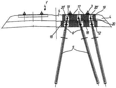
Next, the longitudinal girdersl7 are correctly positioned and installed is
such a way that
the extended heads 18 of the threaded rods extend into corresponding openings
19 in the
longitudinal girders 17 that are of steel or reinforced concrete (Figure 4).
The
longitudinal girders 17 are now set to the exact level and position by means
of
commercially available distance pieces (not shown herein). Ana1ogously to the
transfer
of force between the foundations 5 and the transverse girder 12 that is
effected by the
threaded rods 6, steel plates 20 are fixed by nuts in the openings 19 of the
lon-itudinal
girder 17, between and to the sides of these. on the heads 18 of the threaded
rods of the
connecting sleeves. After a test loading of the system and any required
readjustment and
in connection with precise measurement, the openings 19 in the longitudinal
girder 17 ai-e
closed off by being filled with a quick swelling and fast setting special
mortar.
6
CA 02637208 2008-07-15
WO 2007/082579 PC"F!DE2007/000109
By using the present method, an exactly aligned and new permanent way that can
be
subjected to full loads in a very short time can be prepared in a form that is
not entirely
supported.
A nlajor quantity of the previously removed ballast can be reinstalled beyond
the
constructional connections and to the sides of the longitudinal girder 17 next
to the
adjacent track 1' as well as toward the fi-ee side so that. on the one hand,
sound
attenuation is improved and, on the other, the ground is not sealed.
If necessary, depending on their condition, the original rails 3 can be
reused.
Commercially available connection and support means, for example corrugated
plates,
can be used.
7
CA 02637208 2008-07-15
WO 2007!082579 PCT/DE2007/000109
Parts List
l railway line
1 ' track
track
2 tie
3 rail
4 ballast
4' level
4" level 5 injection pile
5' ground
6 threaded rod\
7 underside of rail
8 caisson
7a
CA 02637208 2008-07-15
NA'O 2007/082579 PCT/DE2007/000109
9 foundation, substructure
head oltlu-eaded rod
11 excavation\
12 transverse girder
13 steel plate
13' nut
14 coiulecting sleeve
transverse girder opening
16 transverse girder upper edge
17 longitudinal girder
18 head of threaded rod, extended
19 longitudinal girder opening
steel plate
20' nut
76