Note : Les descriptions sont présentées dans la langue officielle dans laquelle elles ont été soumises.
CA 02654004 2010-04-12
WO 2007/142977 PCTIUS2007/012754
RELEASE MECHANISMS FOR A CLIP DEVICE
15
TECHNICAL FIELD
(0002) The present invention relates to a clip, and more specifically, to a
clip that can be used
to cause hemostasis of blood vessels along the gastrointestinal tract, or that
can be used as an-
endoscopic tool for holding tissue or the like.
BACKGROUND INFORMATION
[0003) Conventionally, a clip may be introduced into a body cavity through an
endoscope to
grasp living tissue of a body cavity for hemostasis, marking, and/or ligating.
In addition,
clips are now being used in a number of applications related to
gastrointestinal bleeding such
as peptic ulcers, Mallory-Weiss tears, Dieulafoy's lesions, angiomas, post-
papillotomy
bleeding, and small varices with active bleeding.
[0004] Gastrointestinal bleeding is a somewhat common and serious condition
that is often
fatal if left untreated. This problem has prompted the development of a number
of
endoscopic_ therapeutic approaches to achieve hemostasis such as the injection
of sclerosing
l
CA 02654004 2008-12-01
WO 2007/142977 PCT/US2007/012754
agents and contact thermo-coagulation techniques. Although such approaches are
often
effective, bleeding continues for many patients and corrective surgery
therefore becomes
necessary. Because surgery is an invasive technique that is associated with a
high morbidity
rate and many other undesirable side effects, there exists a need for highly
effective, less
invasive procedures.
[0005] Mechanical hemostatic devices have been used in various parts of the
body, including
gastrointestinal applications. Such devices are typically in the form of
clamps, clips, staples,
sutures, etc. that are able to apply sufficient constrictive forces to blood
vessels so as to limit
or interrupt blood flow. One of the problems associated with conventional
hemostatic
devices, however, is that they can only be delivered using rigid shafted
instruments via
incision or trocar cannula. Moreover, many of the conventional hemostatic
devices are not
strong enough to cause permanent hemostasis.
[0006] One proposed solution is described in U.S. Pat. No. 5,766,189, which
shows a clip
device having a pair of arms that are provided with a tendency to open. One
problem with
this clip and other similar types of clips having a pair of arms is that it
may often be
necessary to rotate the clip to properly grasp the area to be clipped.
Rotation of the clip is
often hindered or complicated by the travel of the operating wire through the
bends of the
tube(s) used to deliver the clip. Accordingly, there is a need for a clip that
can be delivered to
the target area and used without having to rotate the clip to a desired
orientation.
[0007] Another problem often encountered with conventional hemostatic devices
is the
difficulty in securing the clip device.to the delivery apparatus prior to
reaching the target area
within the patient, and then quickly and easily releasing the clip device from
the delivery
apparatus once the clip has been attached to the target site.
[0008] Therefore, there is a need for a release mechanism that may quickly and
reliably
disengage the clip device from the delivery apparatus once the clip has been
attached to the
target site.
SUMMARY
[0009] A clip device for living tissue in a body cavity according to the
present invention.
comprises an outer sheath that is insertable into the body cavity. Disposed
within the outer
sheath is an inner sheath. The inner sheath is independently slidable within
the outer sheath.
2
CA 02654004 2008-12-01
WO 2007/142977 PCT/US2007/012754
A clip is provided with a proximal end from which at least two arms extend.
The arms are
formed of a resilient material and are shaped such that the arms are biased or
have a tendency
to be in an open position.
[0010] In a first embodiment, a first retainer is attached to the proximal end
of the clip. An
operating wire is slidably disposed within an inner portion of the inner
sheath, and has a
distal end portion with a second retainer attached to the distal end thereof.
The second
retainer releasably mates with the first retainer to couple the clip to the
operating wire. A
sliding ring is provided and is configured such that when the sliding ring is
moved over the
arms it holds them in a closed position. The sliding ring has a portion that
is sized to contact
the inner sheath so that when the inner sheath is advanced, the sliding ring
slides over the
arms of the clip to close them.
[0011] In one method of operation, the two retainers are joined together and
the sliding ring
is moved to a position such that the sliding ring covers the two retainers. As
a result, the clip
is joined with the operating wire. The outer sheath is advanced to a position
over the clip to
compress or collapse the arms within the device so that it may be passed into
a channel of an
endoscope. When the device is at the target site, the outer sheath is
retracted to expose the
arms, causing them to open radially outward. The inner sheath is advanced,
pushing the
sliding ring over the arms so as to close the arms onto the tissue.
Thereafter, when the inner
sheath is retracted, the retainers may be released, the' device is retracted,
and the clip and first
retainer are left behind.
[0012] Optionally, stop elements, such as beads, may be disposed on the clip
to ensure that
the sliding ring is not advanced distally beyond the end of the clip. Further,
the stop elements
may lockingly engage with the sliding ring to ensure that the sliding ring
does not disengage
from the clip.
[0013] In alternative embodiments, the first retainer may be disengaged from
the second
retainer, for example, by retracting the second retainer with respect to the
first retainer,
rotating the second retainer with respect to the first retainer, or simply
removing the sliding
ring or inner sheath so that they no longer radially restrain the retainers.
[0014] In a further alternative embodiment, an alternative clip is disclosed
comprising at least
two arms having substantially flat regions along part or all of their length.
The proximal ends
of the arms unite at the proximal end of the clip. The proximal end of the
clip has a hole
3
CA 02654004 2011-10-19
formed therein. Various means are disclosed for coupling an operating wire to
the clip using
the hole at the proximal end of the clip.
[0014a] In summary, a clip device for use in endoscopic medical procedures is
provided, the
clip device comprising:
a clip having a plurality of arms each having a proximal end and a distal end,
wherein
the proximal end of each of the arms is joined to a first retainer and extends
distally
therefrom, each of the arms being formed of a resilient material and shaped so
that the distal
ends tend to be spaced apart from each other when the clip is in an open
position and adjacent
to each other when the clip is in a closed position;
a second retainer having proximal and distal regions;
a sliding ring being movable between a first position when the clip is in the
open
position and a second position to hold the arms of the clip in the closed
position; and at
least one stop element disposed on at least one of the arms of the clip,
wherein the first retainer is configured to be disengaged from the second
retainer by
proximally retracting the second retainer with respect to the first retainer.
[0014b] Also provided is a clip device for use in endoscopic medical
procedures comprising:
a clip having a plurality of arms each having a proximal end and a distal end,
wherein the proximal end of each of the arms is joined to a first retainer and
extends distally
therefrom, each of the arms being formed of a resilient material and shaped so
that the distal
ends tend to be spaced apart from each other when the clip is in an open
position and adjacent
to each other when the clip is in a closed position;
a second retainer having proximal and distal regions;
a sliding ring being movable between a first position when the clip is in the
open
position and a second position to hold the arms of the clip in the closed
position; and
at least one stop element disposed on at least one of the arms of the clip,
wherein the first retainer is disengaged from the second retainer by causing
rotation of the
second retainer with respect to the first retainer.
[0015] Other systems, methods, features and advantages of the invention will
be, or will
become, apparent to one with skill in the art upon examination of the
following
figures and detailed description. It is intended that all such additional
systems, methods,
features and advantages be within the scope of the invention, and be
encompassed by the
following claims.
4
CA 02654004 2011-10-19
BRIEF DESCRIPTION OF THE DRAWINGS
[0016] The invention can be better understood with reference to the following
drawings and
description. The components in the figures are not necessarily to scale,
emphasis instead
being placed upon illustrating the principles of the invention. Moreover, in
the figures, like
referenced numerals designate corresponding parts throughout the different
views.
[0017] FIG. 1 is an illustration of one embodiment of a clip device according
to the present
invention.
[0018] FIG. 2 is a partial side-sectional view of a portion of the clip device
of FIG. 1 before
the retainers are joined.
[0019] FIG. 3A is a side-sectional view of a portion of the clip device of
FIG. 1 after the
retainers are joined.
[0020] FIG. 3B is a side-sectional view of an alternative clip device of FIGS.
1-3 A. [0021]
FIG. 3C is a side-sectional view of a further alternative clip device of FIGS.
1-3A.
[0022] FIG. 4 is a side-sectional view of an alternative release mechanism
that may be used to
deploy a clip device.
[0023] FIGS. 5A-5C are, respectively, a side-sectional view of an alternative
release
mechanism that may be used to deploy a clip device, a side-sectional view of
the first retainer
of FIG. 5A after deployment, and a side-sectional view of a further
alternative release
mechanism.
[0024] FIG. 6 is a side view of an alternative release mechanism that may be
used to deploy a
clip device.
30
4a
CA 02654004 2008-12-01
WO 2007/142977 PCT/US2007/012754
[0025] FIGS. 7A-7B are, respectively, a side-sectional view of an alternative
release
mechanism that may be used to deploy a clip device, and an end view showing
the distal end
of the sliding ring of FIG. 7A.
[0026] FIG. 8 is a side-sectional view of an alternative release mechanism
that may be used
to deploy a clip device.
[0027] FIGS. 9A-9B are side-sectional views of alternative'release mechanisms
that may be
used to deploy a clip device.
[0028] FIGS. IOA-10B are side-sectional views of alternative release
mechanisms that may
be used to deploy a clip device.
[0029] FIGS. 11A-11B are, respectively, a side-sectional view of an
alternative release
mechanism that may be used to deploy a clip device, and a side view of the
inner sheath and
sliding ring of FIG. I IA.
[0030] FIG. 12 is a side view of an alternative release mechanism that may be
used to deploy
a clip device.
[0031] FIGS. 13A-13B are, respectively, a side view and a top view of an
alternative clip of
the present invention.
[0032] FIG. 14 is a side-sectional view illustrating a method of deploying the
clip of FIGS.
13A-13B.
[0033] FIG. 15 is a side-sectional view illustrating an alternative method of
deploying the
clip of FIGS. 13A-13B.
[0034] FIG. 16 is a side-sectional view illustrating an alternative method of
deploying the
clip of FIGS. 13A-13B.
[0035] FIG. 17 is a side-sectional view illustrating an alternative method of
deploying the
clip of FIGS. 13A-13B.
[0036] FIGS. 18A-18C are side-sectional views illustrating an alternative
retainer system.
[0037] FIG. 19 is a side-sectional view illustrating a clip retaining
apparatus.
DETAILED DESCRIPTION OF THE PREFERRED EMBODIMENTS
[0038] In the present application, the term "proximal" refers to a direction
that is generally
towards a physician during a medical procedure, while the term "distal" refers
to a direction
that is generally towards a target site within a patent's anatomy during a
medical procedure.
5
CA 02654004 2008-12-01
WO 2007/142977 PCT/US2007/012754
[0039] The present invention provides a clip device for tissue or the like-
Referring to FIGS.
1-3A, a first embodiment of a clip device according to the present invention
is shown. Clip
device 10 includes clip 12 with proximal end 14 having three arms 16 extending
from the
proximal end. Each arm is preferably inwardly bent at its end 18 to better
grasp the tissue.
While three anus are preferred, it is contemplated that fewer than or more
than three arms
may be used. For example, clip 12 may have two or four arms.
[0040] The clip may be made from any suitable resilient material such as
stainless steel,
nitinol, plastic, and the like. In addition, the arms may have a cross-
sectional shape that is
round; square, triangular, pie-shaped, truncated cone, and the like.
[0041] The proximal end 14 of the clip comprises first retainer 20 attached to
the arms. In
one embodiment, the first retainer is permanently attached to the' arms. The
retainer.
preferably is provided with a shape that will complement a shape provided on a
second
retainer so that the first and second retainers will matingly join with each
other. For example,
in the embodiment of FIGS. 1-3A, first retainer 20 has proximal end 22 and
distal end 24,
with notch 26 being disposed therebetween. In this embodiment, proximal end 22
approximates the shape of a half-cylinder having a flat top surface 25, as
depicted in FIG. 3.
As will be explained in moredetail below, this shape advantageously provides
secure mating
with complementary second retainer 60 without increasing the diameter beyond
that of the
first end of the retainer.
[0042] Clip device 10 also compri ses outer sheath 30 (or an introducing tube)
having an inner
diameter that receives inner sheath 40. The inner sheath can be advanced and
retracted
independently of the outer sheath. Inner sheath 40 has an inner diameter that
receives
operating wire 50.
[0043] Outer sheath 30 is attached at its proximal end to forward handle
portion 80. Inner
sheath 40 extends through forward handle portion 80 and is attached at its
proximal end to
middle handle portion 82, which is disposed proximally of the forward handle
portion.
Operating wire 50 extends through the forward and middle handle portions, and
is attached at
its proximal end to rearward handle portion 84, which telescopically extends
over the
proximal portion of the middle handle portion. As will be explained in more
detail below,
longitudinal movement of the operating wire and the inner and outer sheaths
with respect to
each other is controlled by longitudinal manipulation of the forward, middle
and rearward
handles portions with respect to each other.
6
CA 02654004 2008-12-01
WO 2007/142977 PCT/US2007/012754
[0044] Forward handle portion 80 preferably includes flushing port 86. The
flushing port
may comprise a standard male or female luer fitting, or any other valve
mechanism that
permits the injection of fluid therethrough. The flushing port is in fluid
communication with
an interior volume of forward handle portion 80, which in turn is in fluid
communication with
a cavity or gap 88 that is disposed between the inner and outer sheaths.
Accordingly, any
fluid injected through flushing port 86 will necessarily enter cavity 88
between the inner and
outer sheaths, and will subsequently exit cavity 88 near distal end 90 of
outer sheath 30 (see
FIG. 2). In other words, the fluid injected through the flushing port will
exit the clip device
near the clip.
[0045] Alternatively, the cavity can be disposed inside inner, sheath 40, or
either the inner or
the outer sheath may comprise a lumen disposed therein through which fluid can
be passed
along the length thereof. It should also be understood that the flushing port
could be
alternatively located on either of the middle or rearward handle portions, or
on a portion of
the outer sheath distally of any of the handle portions.
[0046] In the embodiment of FIGS. 1-3A, second retainer 60 is attached to the
distal end of
operating wire 50. Preferably, second retainer 60 is complementary to first
retainer 20 so that
the first and second retainers can be matingly joined. Accordingly, second
retainer 60 has
proximal end 64 and distal end 62, with notch 66 being disposed therebetween.
In this
embodiment, distal end 62 approximates the shape of a half-cylinder having a
flat surface 65,
as depicted in FIG. 3A.
[0047] The first and second retainers are joined with each other by locating
flat surface 25 of
first retainer 20 within notch 66 of second retainer 60, and by locating flat
surface 65 of
second retainer 60 within notch 26 of first retainer 20. When joined, the
first and second
retainers form a substantially continuous cylinder shape having substantially
the same outer
diameter from proximal end 64 of second retainer 60 to distal end 24 of first
retainer 20, as
shown in FIG. 3A.
[0048] It will be understood by one of skill in the art that, although first
retainer 20 matingly
joins with second retainer 60, they will not retain a joined position unless
they are held
together. Accordingly, sliding ring 70 is provided and has a first inner
diameter 76 slightly
larger than an outer diameter of first retainer 20 and second retainer 60. In
other words, the
first inner diameter 76 of sliding ring 70 is such that the sliding ring can
slide over the
retainers, yet hold and maintain them in a mating position. In addition,
sliding ring 70 can
7
CA 02654004 2008-12-01
WO 2007/142977 PCT/US2007/012754
slide toward the ends of arms 16 of clip 12, causing the arms to move to a
closed position, as
explained below.
[0049] One possible- method of operation of the first embodiment will be
described. Outside
of the patient's body, outer sheath 30 is retracted to expose inner sheath 40,
operating wire
50, and second retainer 60. Clip 12 is provided and first retainer 20 is
matingly joined with
second retainer 60, as described with respect to FIG. 3A above. Sliding ring
70 is placed
over first retainer 20 and second retainer 60 so that they are maintained in a
joined position.
Sliding ring 70, having the retainers secured therein, then is disposed distal
to inner sheath 40
and within outer sheath 30.
[0050] In a next step, outer sheath 30 is pushed toward the distal end of
inner sheath 40 and
beyond the clip, causing the arms of the clip to close. In this state, outer
sheath 30 is
introduced into a body cavity via a working channel of an endoscope (not
shown) that has
been previously inserted into the body cavity. While the body cavity is
observed via the
endoscope, the distal end portion of outer sheath 30 is guided to a part to be
treated.
[0051] If the part to be treated is obscured by blood or other bodily fluids,
then a fluid such
as saline is injected through flushing port 86 on forward handle portion 80.
The fluid enters
the cavity or gap between inner sheath 40 and outer sheath 30, and exits the
distal end of the
outer sheath. The fluid floods the area so as to flush any blood or bodily
fluids away from the
part to be treated. The injection of fluid is continued and/or repeated as
necessary during the
following steps so as to keep the area free of blood and other bodily fluids.
[0052] Alternatively, a vacuum force may be applied to flushing port 86 so as
to create
suction within the cavity or gap between the inner and outer sheaths. This
suction can be
used to remove blood or other bodily fluids from the area surrounding the part
to be treated.
[0053] In a next step, outer sheath 30 is retracted proximally to expose clip
12, which causes
arms 16 to extend in a radially outward direction, as generally depicted.
Inner sheath 40 is
then advanced towards clip 12, causing sliding ring 70 to slide toward arms 16
of clip 12 and
causing the arms to close, thereby grasping the tissue and facilitating tissue
closure. Inner
sheath 40 is then retracted and when the distal end of the inner sheath passes
the first and
second retainers, they detach and release from each other. Clip 12 is left
inside the body
cavity, holding the tissue. After disengaging the retainers, the clip
operating device is
removed from the channel of the endoscope.
8
CA 02654004 2008-12-01
WO 2007/142977 PCT/US2007/012754
[00541 In the embodiment illustrated, the distal opening 77 of sliding ring 70
has a second
inner diameter smaller than a first diameter on first retainer 20. As a
result, the sliding ring is
not removable from the clip. In this embodiment, the sliding ring can be
located adjacent the
proximal end of the clip so that the arms are in an open position. The sliding
ring can then be
moved to a position toward the ends of the arms to close them.
[0055] Referring now to FIGS. 3B-3C, alternative embodiments of the clip
device of FIGS.
1-3A are described. In FIG. 3B, the three arms 16a-16c of clip 12 comprise
kinks 92a, 92b
and 92c, respectively, which may be formed by bending or warping portions of
the arms as
depicted. The distal opening 77 of sliding ring 70 has a second inner diameter
-configured to
frictionally engage kinks 92a-92c of the three arms 16a-16c. In use, sliding
ring 70 slides
toward the ends of arms 16a-16c of clip 12, causing the arms to move to a
closed position, as
explained above. Once distal opening 77. of sliding ring 70 engages kinks 92a-
92c of arms
16a-16c, respectively, kinks 92a-92c preferably become wedged within. distal
opening 77 and
limit further distal movement of sliding ring 70. In effect, kinks 92a-92c
serve as distal stop
elements to ensure that the sliding ring cannot pass distally over the clip.
[0056] In FIG. 3C, the three arms 16a-16c of clip 12 comprise increased
diameter portions
94a, 94b and 94c, respectively. Increased diameter portions 94a-94c may have
diameters
slightly greater than remaining portions of arms 16a-16c. The distal opening
77 of sliding
ring 70 has a second inner diameter configured to frictionally engage
increased diameter
portions 94a-94c of the three arms 16a-16c. In use, sliding ring 70 slides
toward the ends of
arms 16a-16c of clip 12, causing the arms to move to a closed position, as
explained above.
Once distal opening 77 of sliding ring 70 engages increased diameter portions
94a-94c of
arms 16a-16c, respectively, the increased diameter portions 94a-94c preferably
become
wedged within distal opening 77 and limit further distal movement of sliding
ring 70 to
ensure that the sliding ring cannot pass distally over the clip.
[0057] Referring now to FIGS. 4-12, various alternative release mechanisms for
deploying a
clip device are described. In general, the release mechanisms described in
FIGS. 4-12 may
be used in conjunction with apparatus described in FIGS. 1-3. For example,
outer sheath 30,
inner sheath 40, operating wire 50, sliding ring 70, forward handle portion
80, middle handle
portion 82, rearward handle portion 84 and flushing port 86 may be used in the
embodiments
of FIGS. 4-12. Further, clip 12 may be provided in accordance with the
embodiments
9
CA 02654004 2008-12-01
WO 2007/142977 PCT/US2007/012754
described above, e.g., comprising three arms 16 and preferably having an
inward bend 18 at
its distal end to facilitate hemostasis.
[0058] Referring to FIG. 4, a first alternative embodiment for deploying clip
12-is provided.
Alternative clip device 110 comprises first retainer 120 and second retainer
160. First
retainer 120 is operably attached to arms 16 of clip 12. Proximal end 162 of
second retainer
160 is attached. to operating wire 50, as shown in FIG. 4. First retainer 120
and second
retainer 160 preferably are cylindrical in cross-sectional shape and have
substantially
identical outer diameters when mating, as described below.
[0059] First retainer 120 comprises partially rounded notch 124 formed
therein, and has
rounded knob 125 formed proximal to notch 124. Similarly, second retainer 160
comprises
partially rounded notch 164 formed therein, and has rounded knob 165 disposed
distal to
notch 164. During delivery of the device, rounded knob 165 is aligned with
notch 124, while
rounded knob 125 is aligned with notch 164, as shown in FIG. 4, thereby
securing first
retainer 120 to second retainer 160. In this embodiment, the first and second
retainers are
matingly held together because inner sheath 40 and/or sliding ring 70 at least
partially
overlaps with both retainers, thereby inhibiting movement of the retainers
with respect to
each other.
[0060] In operation, clip device 110 is advanced to a target site through a
working channel of
an endoscope (not shown). The clip device is advanced in the state depicted in
FIG. 4, with
the exception that outer sheath 30 is distally advanced to cover arms 16 of
clip 12 to constrain
the clip within the delivery device. When the desired positioning is
established, outer sheath
is retracted proximally to expose clip 12 and permit radial expansion of arms
16, as
depicted in FIG. 4. In a- next step, inner sheath 40 is advanced distally to
abut sliding ring 70,
causing the sliding ring to be advanced distally towards clip 12 and causing
the arms of clip
25 12 to close radially inward to grasp tissue and promote hemostasis.
[0061] In a next step, inner sheath 40 is retracted proximally past first
retainer 120 and
second retainer 160, thereby exposing the coupling region between the
retainers. At this
time, since the retainers are no longer radially constrained, they will
releasably detach from
one another. It is important to note that since the engaging portions of the
retainers are
30 rounded knobs, it may be less likely that the retainers will get caught on
one another after
deployment. First retainer 120, which is attached to clip 12, remains inside
the body. Second
retainer 160, which is attached to operating wire 50, is retracted via the
operating wire.
CA 02654004 2008-12-01
WO 2007/142977 PCT/US2007/012754
[0062] Referring now to FIGS. 5A-5C, further alternative embodiments for
releasably
securing and deploying clip 12 are provided. Clip device 210 comprises first
retainer 220 and
second retainer 260. First retainer 220 is operably attached to arms 16 of
clip 12, while
second retainer 260 is attached to the distal end of operating wire 50, as
generally described
above. Further, first retainer 220 has socket 222 formed therein, which
preferably comprises
a hole formed laterally therethrough. Channel 224 is disposed between socket
222 and the
proximal end of first retainer 220, as shown in FIG. 5A.
[0063] First retainer 220 further comprises proximal arms 228 and 229, through
which
channel 224 extends. In a preferred embodiment, proximal arms 228 and 229 have
a relaxed
or biased state in which they are bowed radially outward, as shown in FIG. SB.
In this state,
channel 224 is significantly opened.
[0064] Second retainer 260 has wire 265 coupled to its distal end, and further
comprises ball
267 attached to wire 265, as shown in FIG. 5A. During delivery of the device,
wire 265 fits
within channel 224, while ball 267 fits within socket 222, as depicted in FIG.
5A. Therefore,
first retainer 220 is coupled to second retainer 260. The first and second
retainers are
securely held together because inner sheath 40 and/or sliding ring 70 at least
partially
overlaps with both retainers, thereby inhibiting outward movement of the
retainers, and in
particular, proximal arms 228 and 229 of first retainer 220.
[0065] Clip device 210 is advanced to a target site through a working channel
of an
endoscope, as generally described above. During deployment, outer sheath 30 is
retracted
proximally to expose clip 12 and permit radial expansion of arms 16, as shown
in FIG. 5A.
Inner sheath 40 then is advanced distally to abut sliding ring 70, causing the
sliding ring to be
advanced distally towards clip 12 and causing the arms of clip 12 to close
inward to grasp
tissue and promote hemostasis, as described above. In a next step, inner
sheath 40 is
retracted proximally past first retainer 220 and second retainer 260, thereby
exposing the
coupling region between the retainers. At this time, since proximal arms 228
and 229 are no
longer radially constrained, they assume the configuration shown in FIG. 5B
and permit ball
267 to detach from socket 222. First retainer 220, which is attached to clip
12, remains inside
the body, while second retainer 260 is retracted via operating wire 50. In an
alternative
embodiment, second retainer 260 is eliminated and ball 267 is connected
directly to operating
wire 50.
CA 02654004 2008-12-01
WO 2007/142977 PCT/US2007/012754
[0066] In a further alternative embodiment, and as illustrated in FIG. 5C,
first retainer 220'
comprises angled channel 222' formed therein. Angled channel 222' may be
formed partially
through first retainer 220', or bored all the way through. Preferably, angled
channel 222' is
formed partially through the proximal end of first retainer 222', thereby
forming a space
through which operating wire 50 may extend. The distal end of operating wire
50 is coupled
to ball 267', which is captured within channel ' 222' when covered by inner
sheath 40 or
sliding ring 70, as depicted in FIG. 5C. Once sliding ring 70 is advanced
distally and/or inner
sheath 40 retracted proximally, operating wire 50 may be retracted proximally
and ball 267'
will exit the proximal end of angled channel 222' to disengage the clip from
the delivery
apparatus.
[0067] Referring now to FIG. 6, a side view of a further alternative mechanism
for deploying
clip 12 is provided. Clip device 310 comprises first retainer 320 and second
retainer 360,
which are releasably secured together by loop member 363. For illustrative
purposes, outer
sheath 30, inner sheath 40, and sliding ring 70 are omitted from FIG. 6,
although they
preferably are provided in accordance with the embodiments described above. In
this
embodiment, first retainer 320 preferably comprises notch 325 formed therein
and has hook
member 326 disposed proximal to the notch, as shown in FIG. 6. Second retainer
360 has a
proximal end attached to operating wire 50, and has a distal end having loop
member 363
extending therefrom.
[0068] In operation, loop member 363 is placed over hook member 326, as shown
in FIG. 6,
thereby securely coupling first retainer 320 to second retainer 360. Sliding
ring 70 is
advanced over at least notch 325 to ensure that loop member 363 cannot be
inadvertently
detached. Clip device 310 then is advanced to a target site through a working
channel of an
endoscope, as generally described above. During deployment, outer sheath 30 is
retracted
proximally to expose clip 12 and permit radial expansion of arms 16. Inner
sheath 40 is
advanced distally to abut sliding ring 70, causing the sliding ring to be
advanced distally
towards clip 12 and causing the arms of clip 12 to close inward, as described
above. Inner
sheath 40 then is retracted proximally to uncover first retainer 320 and
second retainer 360.
At this time, loop member 363 is no longer radially constrained about hook
member 326,
which permits first retainer 320 to disengage from second retainer 360. The
proximal face of
hook member 326 can be angled to facilitate movement of loop member 363 out of
notch
12
CA 02654004 2008-12-01
WO 2007/142977 PCT/US2007/012754
325. After the retainers have separated, all of the components (except clip 12
attached to first
retainer 320) are removed through the working channel of the endoscope.
[0069] In an alternative embodiment to FIG. 6, second retainer 360 may be
eliminated and
operating wire 50 may comprise a loop member, i.e., similar to loop member
363, at its distal
end. In this case, the loop member of operating wire 50 is directly coupled to
hook member
326 of first retainer 320.
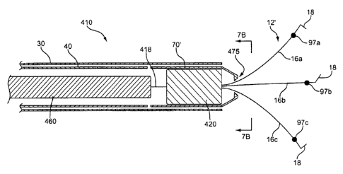
[0070] Referring now to FIGS. 7A-7B, a further alternative embodiment for
releasably
securing and deploying a clip device is provided. In FIG. 7A, clip device 410
comprises first
retainer 420 and second retainer 460, which are releasably secured together by
frangible
element 418. The frangible element is designed to break apart in a controlled
manner when a
sufficient tensile force is imposed upon it, as explained in more detail
below. In FIG. 7A,
second retainer 460 is shown in the form of a cable that extends proximally
within inner
sheath 40. If desired, operating wire 50 may be coupled to a proximal region
of second
retainer 460 in a fashion similar to the other embodiments described above.
Alternatively,
second retainer 460 may be omitted and operating wire 50 may be coupled
directly to first
retainer 420, wherein operating wire 50 may comprise an integrally formed,
frangible distal
region.
[0071] Further, in this embodiment, clip 12' comprises three arms 16a, 16b and
16c having
stop elements 97a, 97b and 97c, respectively. The stop elements preferably
comprise a bead-
shaped, oval-shaped, or circular-shaped metal material, or any other suitable
shape. The stop
elements may be disposed on an outer surface of one or more of arms 16a, 16b
and 16c and
soldered or otherwise attached proximal to ends 18 of the arms. Alternatively,
the stop
elements may be formed integrally with their respective arms during
manufacture. Stop
elements 97a, 97b and 97c serve multiple purposes. One purpose is to ensure
that sliding ring
70' cannot be advanced over the distal end of clip 12'. Another purpose is to
limit the
amount of closing force that can be applied to arms 18 of clip 12'. Still
another purpose of
the stop elements is to engage distal end 475 of sliding ring 70' to
facilitate disengagement of
the first retainer from the second retainer, e.g., when retracting the second
retainer with
respect to the first retainer, or rotating the retainers with respect to each
other, as explained
more fully below.
[0072] When the stop elements are employed, distal end 475 of sliding ring 70'
preferably
comprises three-channels 497a, 497b and 497c (see FIG. 7B) which are
configured to permit
13
CA 02654004 2008-12-01
WO 2007/142977 PCT/US2007/012754
movement of arms 16a, 16b and 16c therethrough, respectively. However, stop
elements 97a,
97b and 97c are sized so that they cannot pass completely through the
channels. Therefore,
when sliding ring 70' is advanced distally over clip 12', arms 16a, 16b and
16c pass through
channels 497a, 497b and 497c, respectively, but the stop elements serve as
distal stop
elements to ensure that the sliding ring cannot pass distally over the clip.
[0073] In a preferred embodiment, sliding ring 70' preferably comprises
depressions 498a,
498b and 498c, which extend from the distal tip of sliding ring 70' into
channels 497a, 497b
and 497c, respectively (see FIG. 7B). Stop elements 97a, 97b and 97c
preferably are sized to
be at least partially seated within depressions 498a, 498b and 498c,
respectively. In one
embodiment, the stop elements may lockingly engage their respective
depressions, e.g., using
a snap-fit, thereby ensuring that sliding ring 70' cannot disengage from clip
12'.
[0074] In operation, clip device 410 is advanced to a target site through a
working channel of
an endoscope, as generally described above. The proximal end of first retainer
420 is
coupled to the distal end of second retainer 460 using frangible element 418.
During
deployment, outer sheath 30 is retracted proximally to expose clip 12 and
permit radial
expansion of arms 16. Inner sheath 40 is advanced distally to abut sliding
ring 70', causing
the sliding ring to be advanced distally towards clip 12' and causing the arms
of clip 12' to
close inward, as described above. Stop elements 97a, 97b and 97c engage
depressions 498a,
498b and 498c, respectively, to ensure that the sliding ring is not advanced
distally past the
end of the clip.
[0075] In a next step, inner sheath 40 is held steady while second retainer
460 (or operating
wire 50 coupled to second retainer 460) is retracted proximally. The
retraction of second
retainer 460 with respect to first retainer 420 imposes a tensile force upon
frangible element
418, thereby breaking the frangible element and detaching the retainers. Based
on tactile
feedback, a physician will be able to sense when the frangible element has
been broken and
the retainers have detached.
[0076] It should be noted that during proximal retraction of second retainer
460, clip 12' will
be held steady and not displaced from engagement with the tissue.
Specifically, after sliding
ring 70' has been advanced distally and has engaged stop elements 97a, 97b and
97c, the stop
elements prohibit proximal retraction of clip 12' with respect to sliding ring
70'. Since inner
sheath 40 is held steady and prevents proximal retraction of sliding ring 70',
clip 12' cannot
14
CA 02654004 2008-12-01
WO 2007/142977 PCT/US2007/012754
be retracted proximally, either. This helps prevent excessive forces from
being applied to the
tissue.
[0077] Referring now to FIG. 8, a further alternative embodiment for
releasably securing and
deploying a clip, such as clip 12', is provided. In FIG. 8, clip 12' and
sliding ring 70'
preferably are provided as described in FIGS. 7A-7B above. Therefore, clip 12'
comprises
stop elements 97a, 97b and 97c, which are sized to be at least partially be
seated within
depressions 498a, 498b and 498c, respectively, at the distal end of sliding
ring 70' (see FIG.
7B).
[0078] Clip device 510 comprises first retainer 520 and second retainer 560,
which are
releasably secured together by magnetic forces, i.e., first retainer 520 has a
first magnetic
force and second retainer 560 has an opposing magnetic force. In operation,
inner sheath 40
is advanced distally to cause sliding.ring 70' to close arms 16a, 16b and 16c.
When sliding
ring 70' is advanced distally, stop elements 97a, 97b and 97c of clip 12'
engage the
depressions in sliding ring 70'. Inner sheath 40 then is held steady while
operating wire 50 is
retracted proximally, thereby overcoming the magnetic force and causing second
retainer 560
to detach from first retainer 520. In effect, distal end 564 of second
retainer 560 separates
from proximal end 522 of first retainer 520, and second retainer 560 becomes
retracted
further proximally within. inner sheath 40. After the retainers have
separated, inner sheath 40
is retracted proximally, and all of the components (except clip 12' attached
to first retainer
520) are removed through the working channel of the endoscope.
[0079] Referring now to FIGS. 9A-9B, further alternative embodiments for
deploying a clip,
such as clip 12', are provided. In -FIG. 9A, clip 12' and sliding ring 70'
preferably are
provided as described in FIGS. 7A-7B above. Therefore, clip 12' comprises stop
elements
97a, 97b and 97c, which are sized to be at least partially be seated within
depressions 498a,
498b and 498c, respectively, at the distal end of sliding ring 70' (see FIG.
7B).
[0080] Clip device 610 comprises first retainer 620 and second retainer 660,
which are
releasably secured together by a ball bearing and detent arrangement.
Specifically, first
retainer 620 has inner bore 627 formed in its proximal end. Ball elements 642
and 643 are
coupled to opposing exterior regions of first retainer 620 and partially
extend into bore 627,
as shown in FIG. 9A. The ball elements also extend radially outward towards
sliding ring
70'; and preferably contact the sliding ring, as depicted in FIG. 9A. Ball
elements 642 and
643 are movable, but not removable, relative to- first retainer 620.
CA 02654004 2008-12-01
WO 2007/142977 PCT/US2007/012754
[0081] Second retainer 660 has an outer diameter that is less than the
diameter of bore 627 of
first retainer 620, thereby allowing second retainer 660 to be disposed within
the bore.
Second retainer 660 also has opposing notches 662 and 663 formed therein,
which are sized
to receive an outer portion of ball elements 642 and 643, respectively, as
described below.
[0082] In operation, clip device 610 is advanced to a target site through a
working channel
of an endoscope, as generally described above. During advancement, sliding
ring 70' and/or
inner sheath 40 are disposed over ball elements 642 and 643, thereby urging
the ball elements
in an inward direction into a portion of notches 662 and 663, respectively.
When urged
radially inward towards the notches, ball elements 642 and 643 substantially
prohibit
longitudinal movement of first retainer 620 with respect to second retainer
660, as shown in
FIG. 9A.
[0083] During deployment, outer sheath 30 is retracted proximally to expose
clip 12' and
permit radial expansion of arms 16. Inner sheath 40 is advanced distally to
abut sliding ring
70', causing the sliding ring to be advanced distally towards clip 12' and
causing the arms of
clip 12' to close inward, as described above. Inner sheath 40 then is
retracted proximally past
second retainer 660. When sliding ring 70' and/or inner sheath 40 no longer
constrain ball
elements 642 and 643, the ball elements are permitted to move radially
outward, i.e., out of
notches 662 and 663. At this time, second retainer 660 may be retracted
proximally via
operating wire 50, and ball elements 642 and 643 will not catch on their
respective detents.
Alternatively, ball elements 642 and 643 may be deformable when subjected to a
sufficient
tensile release force.
[0084] The embodiment of FIG. 9B is similar to that described in FIG. 9A, with
a main
exception that one or more rivet elements 642' and 643' are employed in lieu
of ball elements
642 and 643. Rivet element 642' preferably comprises a first end having flat
surface 652 and
a second end having enlarged rounded' region 653. A smaller diameter portion
extends
between flat surface 652 and rounded region 653. The smaller diameter portion
is disposed
through a hole in first retainer 620', as shown in FIG. 9B, to contain rivet
element 642'. 'In
operation, when sliding ring 70' and/or inner sheath 40 are disposed over
first retainer 620',
rivet element 642' is urged radially inward, thereby urging rounded region 653
into notch
662' in second retainer 660' to secure the first retainer to the second
retainer. When sliding
ring 70' and/or inner sheath 40 no longer constrain rivet 642', it may move
radially outward
16
CA 02654004 2008-12-01
WO 2007/142977 PCT/US2007/012754
and will not catch on notch 662'. Therefore, second retainer 660' may
disengage from first
retainer 620'.
[0085] Referring now to FIGS. 10A-10B, variations on the embodiment described
in FIGS.
9A-9B are shown. In FIG. 10A, clip device 710 preferably comprises two
opposing ball
elements 742 and 743 that selectively permit coupling of first retainer 720
and second
retainer 760.
[0086] First retainer 720 has inner bore 727 formed in its proximal end, which
is adapted to
receive a reduced diameter distal region of second retainer 760, as shown in
FIG. 10A. First
retainer 720 further comprises first and second notches 722 and 723 formed in
bore 727,
while the distal region of second retainer 760 has recesses 762 and 763 formed
therein.
Recesses 762 and 763 are configured to contain a substantial portion of ball
elements 742 and
743, respectively, while a portion of the ball elements may extend outside of
the confines of
the recesses, as depicted in FIG. 10A. The recesses are configured, however,
to never permit
the ball elements to escape therefrom.
[0087] In a preferred embodiment, biasing means 775, e.g., a compression
spring, is
disposed within recess 762. The biasing means is disposed beneath ball element
742 to bias
the ball element radially outward, i.e., towards notch 722. A second biasing
means (not
shown) preferably is used to bias ball element 743 radially outward in the
same manner.
[0088] In operation, clip device 710 is advanced to a target site through a
working channel of
an endoscope, as generally described above. During advancement, ball elements
742 and 743
are aligned with notches 722 and 723, respectively. The biasing means bias
their respective
ball elements. radially outward into their respective notches to securely
couple first retainer
720 to second retainer 760.
[0089] After deployment of clip 12', inner sheath 40 is advanced distally and
held steady
against sliding ring 70'. At this time, second retainer 760 may be retracted
proximally via
operating wire 50. Stop elements 97a, 97b and 97c may engage depressions 498a,
498b and
498c, respectively, in sliding ring 70' (see FIG. 7B). The intentional
retraction of second
retainer 760 by a physician will overcome the force provided by biasing means
775, thereby
causing ball elements 742 and 743 to be forced radially inward and permitting
disengagement
of the two retainers. Alternatively, ball elements 742 and 743 may be
deformable when
subjected to a sufficient tensile release force. Once detached, second
retainer 760 may be
17
CA 02654004 2008-12-01
WO 2007/142977 PCT/US2007/012754
retracted via inner sheath 40, while first retainer 720 attached to clip 12'
is left inside the
patient.
[0090] The embodiment of FIG. IOB is similar to that described in FIG. 10A,
with' a main
exception that one or more biased elements 742' and 743' are employed in lieu
of ball
elements 742 and 743. Biased elements 742' and 743' preferably are integrally
formed with
reduced diameter distal region 765 of second retainer 760', as shown in FIG.
10B. Biased
elements 742' and 743' have a predetermined configuration in which they are
biased radially
outward into notches 722' and 723', respectively, to secure second retainer
760' to first
retainer 720'. When it is desired to disengage the retainers, second retainer
760' is retracted
proximally with respect to first retainer 720' to urge biased elements 742'
and 743' radially
inward, i.e., out of notches 722' and 723'. Therefore, second retainer 760'
may disengage
from first retainer 720'.
[0091] In the embodiments of FIGS. 9-10, it will be apparent that although two
opposing ball
elements are shown, only one ball element may be employed, or alternatively,
three or more
may be used. Additionally, while ball-shaped elements are depicted, it will be
apparent that
these elements may comprise other shapes, such as oval-shaped elements, cone-
shaped
elements, and so forth.
[0092] Referring now to FIGS. I IA-1IB, a further alternative embodiment of
the present
invention is described. In FIGS. 11A-11B, clip 12' comprises stop elements
97a, 97b and
97c, which are sized to be at least partially be seated within depressions
498a, 498b and 498c,
respectively, at distal end 475 of sliding ring 70' (see FIG. 7B). Clip device
810 comprises
first retainer 820 and second retainer- 860. First retainer 820 has bore 825
formed in its
proximal end. Bore 825 has internal threading 827, which is configured to
releasably mate
with external threading 862, which is disposed on a distal region of second
retainer 860.
Torque cable 815 is coupled to a proximal region of second retainer 860 and
preferably spans
the entire length of the delivery system.
[0093] In the embodiment of FIGS. 11A-11 B, inner sheath 40' and sliding ring
70" are
similar to the embodiments described above. However, the distal end of inner
sheath 40' is
configured to mate with the proximal end of sliding ring 70" to inhibit
rotational movement
therebetween, for purposes explained below. In one embodiment, the distal end
of inner
sheath 40' comprises at least one notch 442 that is configured to mate with at
least one
18
CA 02654004 2008-12-01
WO 2007/142977 PCT/US2007/012754
corresponding knob 443 extending from the proximal end of sliding ring 70", as
shown in
FIG. I1B.
[0094] In operation, clip device 810 is advanced to a target site through a
working channel of
an endoscope, as generally described above. During advancement, first retainer
820 is
secured to second retainer 860 by engaging their respective internal and
external threaded
regions. After clip 12' is deployed, as described above, torque cable 815 is
rotated in a
'direction that causes the threaded regions to disengage. Once the first and
second retainers
are disengaged, torque cable 815 and second retainer 860 may be retracted
proximally via
inner sheath 40', while first retainer 820 attached to clip 12' is left inside
the patient.
[0095] In this particular embodiment, once sliding ring 70" has been advanced
distally by
inner sheath 40', stop elements 97a, 97b and 97c engage the depressions in
sliding ring 70".
As noted above, the stop elements may lock into engagement with the
depressions in sliding
ring 70", e.g., using a snap-fit. Further, notches 442 of inner sheath 40'
mate with
corresponding knobs 443 of sliding ring 70" (see FIG. I IB) to prevent
rotational movement
of the inner sheath with respect to the sliding ring. Therefore, by holding
inner sheath 40'
steady while rotating torque cable 815 relative thereto, second retainer 860
is rotated with
respect to first retainer 820, thereby causing the retainers to disengage. In
other words, by
holding inner sheath 40' rotationally steady, sliding ring 70" cannot rotate
(see FIG. 11B),
and therefore, clip 12' cannot rotate because stop elements 97a, 97b and 97c
are restrained
within the depressions 498a, 498b and 498c of the rotationally-steady sliding
ring.
[0096] Referring now to FIG. 12, a further alternative embodiment of the
present invention is
described. In FIG. 12, clip device 910 comprises first retainer 920 and second
retainer 960.
For illustrative purposes, the outer sheath, inner sheath, and sliding ring
are omitted from
FIG. 12. First retainer 920 has bore 925 formed in its proximal end, and
further comprises
first and second inwardly-directed knobs 927 and 928 projecting into bore 925,
as shown in
FIG. 12. Second retainer 960 has proximal and distal ends, and further has an
outer diameter
that is slightly smaller than an inner diameter of bore 925. Axial channels
967 and 968 are
formed in the distal end of second retainer 960, preferably 180 degrees apart,
and extend
longitudinally from the distal end towards the proximal end, as shown in FIG.
12. Before
reaching the proximal end, axial channel 967 transitions into circumferential
channel 977,
which preferably extends about 90 degrees around the outer circumference of
second retainer
19
CA 02654004 2008-12-01
WO 2007/142977 PCT/US2007/012754
960. Similarly, axial channel 968 transitions into circumferential channel
978, which extends
about 90 degrees around the outer circumference of second retainer 960, as
shown in FIG. 12.
[0097] Channels 967, 968, 977 and 978 preferably are etched into an exterior
surface of
second retainer 960, which may be formed of stainless steel or the like. Knob
927 of first
retainer 920 is sized for movement within channels 967 and 977, while knob 928
is sized for
movement within channels 968 and 978, as described below.
[0098] In operation, clip device 910 is advanced to a target site through a
working channel of
an endoscope, as generally described above. During advancement, first retainer
920 is
secured to second retainer 960 by aligning knobs 927 and 928 with axial
channels 967 and
10. 968, respectively. Second retainer 960 is moved towards first retainer 920
to cause the knobs
to slide within their respective axial channels. When knobs 927 and 928 reach
the proximal
portion of their respective axial channels, second retainer 960 is rotated
about 90 degrees
with respect to first retainer 920, thereby causing knobs 927 and 928 to be
advanced within
their respective circumferential channels 977 and 978. In this state, first
and second retainers
920 and 960 are coupled together, and longitudinal movement of the retainers
with respect to
each other is substantially prohibited.
[0099] Clip .12' may then be deployed and secured to tissue by advancing
sliding ring 70" of
FIG. 11B. In a next step, torque cable 915, which is operably coupled to the
proximal end of
second retainer 960, is rotated about 90 degree in a direction opposite the
direction used to
lock the retainers together. This rotation causes knobs 927 and 928 to be
aligned with: axial
channels 967 and 968, respectively. At this time, second retainer 960 may be
retracted
proximally to cause knobs 927 and 928 to slide within axial channels 967 and
968,
respectively, thereby unlocking the retainers. Once the first and second -
retainers are
disengaged, torque cable 915 and second retainer 960 may be retracted
proximally through
inner sheath 40, while first retainer 920 attached to clip 12 is left inside
the patient. It will be
apparent that although two opposing knobs are shown in FIG. 12, only one
knob/channel
arrangement may be employed, or alternatively, three or more may be used.
[00100] In this embodiment, clip device 910 preferably employs clip 12', inner
sheath 40'
and sliding ring 70", as described in FIGS. I IA-11B above. As noted above,
the use of such
interlocking components will hold clip 12' rotationally stationary while
second retainer 960 is
rotated with respect to first retainer 920.
CA 02654004 2008-12-01
WO 2007/142977 PCT/US2007/012754
[00101] Referring now to FIGS. 13-17, various alternative embodiments of the
present
invention are described. Alternative clip 1012 comprises at least two arms,
and in the
embodiment of FIGS. 13A-13B, comprises three arms 1016a, 1016b and 1016c, each
having
proximal and distal ends. The distal ends of arms 1016a, 1016b and 1016c
comprise bends
1018a, 1018b and 1018c, respectively, which are configured to engage tissue.
[00102] In general, clip 1012 is similar to clip 12, described above, with the
main exception
that arms 1016a, 1016b and 1016c comprise substantially flat regions along
part or all of their
length, as shown in FIGS. 13-13B. Moreover, the proximal ends of arms 1016a,
1016b and
1016c unite to form proximal end 1020 of clip 1012. Clip 1012 may be formed by
cutting a
flat clip having the desired number of arms (e.g., three) from a planar sheet
of material, then
bending the arms into the desired final shape. Proximal end 1020 has hole 1028
disposed
therein, as shown in FIG. 13B. Optionally, at least one slit 1029 may be
formed around the
circumference of hole 1028, for purposes described below.
[00103] Referring now to FIG. 14, a first method of using clip 1012 of FIGS.
13A-13B is
described. The apparatus comprises outer sheath 1030 and inner sheath 1040,
which are
similar to outer sheath 30 and inner sheath 40, as described above. The distal
end of inner
sheath 1040 is configured to engage collet 1070, which is disposed about the
proximal end of
clip 1012 and designed to close the clip, as explained below. Preferably, arms
1016a, 1016b
and 1016c comprise distal stop members 1025a, 1025b and 1025c, as shown in
FIG. 13A and
FIG. 14. The distal stop members ensure that collet 1070 cannot be advanced
distally over
the clip. Collet 1070 is similar in design and function to sliding ring 70,
70' of the above-
described embodiments.
[00104] In FIG. 14, clip 1012 is coupled to operating wire 1050 prior to
deployment. The
distal end of operating wire 1050 is coupled to frangible member 1052, which
in turn is
coupled to knob 1054, as shown in FIG. 14. Alternatively, frangible member
1052 may be
integrally formed at the distal end of operating wire 1050. Frangible member
1052 extends
through hole 1028 in proximal end 1020 of clip 1012, such that knob 1054 is
confined distal
to hole 1028, as shown in FIG. 14.
[00105]= Clip 1012 is advanced to a target site with arms 1016a, 1016b and
1016c radially
restrained by outer sheath 1030. Outer sheath 1030 is retracted to cause arms
1016a, 1016b
and 1016c to deploy radially outward, as shown in FIG. 14 and generally
described above. In
a next step, inner sheath 1040 is advanced distally to abut collet 1070 and
distally advance
21
CA 02654004 2008-12-01
WO 2007/142977 PCT/US2007/012754
collet 1070 over arms 1016a, 1016b and 1016c. The arms are urged radially
inward to
engage tissue and promote hemostasis.
[00106] When collet 1070 abuts distal stop members 1025a, 1025b and 1025c,
inner sheath
1040 is held steady while operating wire 1050 is retracted proximally. At this
time, knob
5. 1054 engages hole 1028 but cannot be pulled through the hole. The tensile
force causes
frangible member 1052 to break, thereby separating clip 1012 from operating
wire 1050. The
outer sheath, inner sheath and operating wire are then removed from the
patient.
[00107] Referring now to FIGS. 15-17; various alternative release mechanisms
for deploying
clip 1012 of FIGS. 13A-13B are described- In FIG. 15, wire 1150 is advanced
distally
through hole 1028 of clip 1012, then loop 1152 is formed, and wire 1150 is
pulled back
through hole 1028. In a relaxed state, loop. 1152 is secured distal to hole
1028, i.e., the loop
will not pull through the hole in the absence of a significant force. In use,
collet 1070 is
advanced via inner sheath 1040 and abuts distal stop members 1025a, 1025b and
1025c.
Inner sheath 1040 then is held steady while wire 1150 is retracted proximally.
At this time,
an inwardly directed force causes loop 1152 to compress and pull through hole
1028, thereby
separating clip 1012 from wire 1150.
[00108] In FIG- 16, the distal end of operating wire 1250 extends through hole
1028 and is
coupled to knob 1252, which is disposed distal to hole 1028. In use, collet
1070 is advanced
via inner sheath 1040 and abuts distal stop members 1025a, 1025b and 1025c.
Inner sheath
1040 then is held steady while wire 1250 is retracted proximally. At this
time, knob 1252
pulls through hole 1028, thereby separating clip 1012 from operating wire
1050. Preferably,
in this embodiment, at least one slit 1029 (see FIG. 13B) is employed. to
facilitate retraction
of knob 1252 through hole 1028.
[00109] In FIG. 17, the distal end of operating wire 1350 is coupled to
deformable member
1354. In this example, deformable member 1354 comprises at least two arms that
extend
radially outward in a relaxed state. The arms of deformable member 1354 may be
coupled to
rigid proximal section 1352, which in turn is coupled to operating wire 1350,
as shown in
FIG. 17. Alternatively, operating wire 1350 may be coupled directly to
deformable member
1354.
[00110] In use, proximal section 1352 (or operating wire 1350).or is disposed
through hole
1028, while deformable member 1354 is disposed distal to hole 1028, as shown
in FIG. 17.
Collet 1070 is advanced via inner sheath 1040 and abuts distal stop members
1025a, 1025b
22
CA 02654004 2008-12-01
WO 2007/142977 PCT/US2007/012754
and 1025c, and inner sheath 1040 then is held steady while operating wire 1350
is retracted
proximally. At this time, the arms of deformable member 1354 are urged
radially inward to
pull deformable member 1354 through hole 1028, thereby separating clip 1012
from
operating wire 1350. In this embodiment, at least one slit 1029 (see FIG. 13B)
may be
employed to facilitate retraction of deformable member 1354 through hole 1028.
[00111] Referring now to FIGS. 18A-18C, a further alternative clip retainer
system is shown.
First retainer 1420 has proximal and distal regions 1428 and 1425. Distal
region 1425
comprises a generally cylindrical shape and is attached to clip 12. Proximal
region 1428
preferably has a smaller diameter than distal region 1425, and may comprise a
rounded
proximal edge, as depicted in FIG. 18A. At least one notch 1427 is disposed
between the
proximal and distal regions, as shown in FIG. 18A.
[00112] Second retainer 1460 comprises a generally cylindrical body having
proximal and
distal regions. The proximal region is attached to operating wire 1450. The
distal region
comprises bore 1465 having at least one knob 1463 extending therein, as shown
in FIG. 18A.
Further, an exterior surface of second retainer 1460 has at least one
protruding member 1462
extending radially outward, as depicted in FIG. 18A.
[00113] In the embodiment of FIGS. 18A-18C, sliding ring 1470 is disposed over
first
retainer 1420, as shown in FIG. 18A. Sliding ring 1470 comprises a flexible
proximal region,
as will be explained in FIG. 18B. Optionally, sliding ring 1470 may comprise a
lateral slit
(not shown) disposed on a proximal region to enhance its radial flexibility
and accommodate
second retainer 1460, as explained below.
[00114] In operation, a physician may attach second retainer 1460 to first
retainer 1420 by
distally advancing second retainer 1460. As shown in FIG. 18B, protruding
member 1462
causes radial expansion of a proximal region of sliding ring 1470. At this
time, knob 1463 is
passed over proximal region 1428 of first retainer 1420, preferably with
little or no resistance.
As second retainer 1460 is further advanced, proximal region 1428 of first
retainer 1420 is
disposed within the confines of bore 1465. Moreover, this placement allows
sliding ring
1470 to exert a resilient inward force upon protruding member 1462, thereby
urging knob
1463 into notch 1427, as shown in FIG. 18C.
[00115] In a next step, an inner and outer sheath may be disposed over the
apparatus and
inserted into the patient, as generally set forth above. After the inner
sheath advances sliding
ring 1470 in a distal direction to close the arms of clip 12, second retainer
1460 may be
23
CA 02654004 2008-12-01
WO 2007/142977 PCT/US2007/012754
retracted proximally via operating wire 1450 to allow knob 1463 to disengage
from notch
1427, thereby separating the retainers.
[00116] Referring now to FIG. 19, an apparatus that may be used to hold
multiple clips is
disclosed. Clip holder 1502 comprises proximal region 1508 and enlarged
diameter distal
region 1504. A taper 1507 is provided between the proximal and distal regions.
Multiple
clips 1520a, 1520b and 1520c are adapted to be pre-loaded into proximal region
1508, as
shown in FIG. 19. The arms 1512 of clips 1520a-c may be nested within bores
1530 of
adjacent clips, or disposed proximal to adjacent clips as shown. First
retainers 1520a-c may
comprise portions adapted to mate with complementary portions on second
retainer 1560.
For example, ball element 1562 may be adapted to engage with notch elements
1532 of
second retainers 1520a-c. Advantageously, each time a new clip is needed, a
physician may
simply insert second retainer 1560 into clip holder 1502, engage a clip, and
proceed to deploy
the clip within a patient according the steps generally set forth above.
[00117] While various embodiments of the invention have been described, it
will be apparent
to those of ordinary skill in the art that many more embodiments and
implementations are
possible within the scope of the invention. Accordingly, the invention is not
to be restricted
except in light of the attached claims and their equivalents.
24