Note : Les descriptions sont présentées dans la langue officielle dans laquelle elles ont été soumises.
CA 02752764 2016-01-15
1
Quick release door hinge system
FIELD OF THE INVENTION
[001] The present invention relates generally to hinges but more particularly
to
a quick release door hinge system.
BACKGROUND OF THE INVENTION
[002] Door hinges have been around for centuries. They consist of two plates
joined by way of a pin. The pin has to be removed in order for the two
plates to be separated and thus allow the removal of the door. Removing
the pin often requires hand tools and takes time to accomplish. During
installation, aligning the two parts can sometimes be challenging on a
heavy door having three sets of hinges as all three sets have to be
aligned before a single pin can be inserted.
SUMMARY OF THE INVENTION
[003] In view of the foregoing disadvantages inherent in the known devices
now present in the prior art, the present invention, which will be
described subsequently in greater detail, is to provide objects and
advantages which are:
CA 02752764 2016-01-15
2
[004] To provide for a door hinge system that accelerates the installation of
a
door on its hinges.
[005] Another advantage of this invention is to provide for a means to
eliminate tampering which could lead to unwanted release from the
hinges.
[006] To attain these ends, the present invention generally comprises a jamb
flap adapted to be fixedly attached to a door jamb, and including at least
two jamb flap barrels further comprised of channel members. A door flap
adapted to be fixedly attached to a door and including at least two door
flap barrels further comprised of channel members. The at least two
door flap channel members including at least two pin members inserted
into the at least two door flap channel members, and the at least two pin
members adapted to be received within respective jamb flap channel
members of the jamb flap, such that when the pin members are placed
within respective jamb flap channel members the two flap members are
pivotable to one another, and a locking pin member adapted to be
placed between the jamb flap channel member and the door flap
channel member to thereby block the removal of the door flap pin
members from the jamb flap channel members, and thereby prevent the
disconnection between the door flap and the jamb flap.
CA 02752764 2016-01-15
3
[007] Barrels centrally located on a vertical axis and bevels of screw holes
located on both faces of the jamb flap and door flap to allow for jamb
flap and door flap to be used on left and right side.
[008] The locations of the jamb flap and the door flap are adapted to be
reversible.
[009] The jamb flap and the door flap are made from a metallic material; and
the locking pin member is magnetic and adapted to magnetically attach
between the jamb flap channel member and the door flap channel
member when the door flaps are pivotally connected with the jamb flaps,
to thereby stay in place yet be easily removable by hand.
[0010] The door hinge system has three jamb flap channel members and three
door flap pin members.
[0011] A method of pivotally attaching a door member to a door jamb, the
method comprising the steps of:
[0012] a.) Providing a doorjamb.
[0013] b.) Providing a door.
CA 02752764 2016-01-15
4
[0014] c.) Providing at least two hinge systems, wherein each hinge system
comprises a jamb flap adapted to be fixedly attached to the door jamb,
and including at least two channel members adapted to receive door
flap pin members therein. A door flap adapted to be fixedly attached to
the door, and including at least two pin members adapted to be received
within respective channel members of the jamb flap, such that when the
door flap pin members are placed within respective jamb flap channel
members the two flap members are pivotable to one another. And a
locking pin member adapted to be placed between two of the at least
two channel members to thereby block the removal of the door flap pin
members from the jamb flap channel members, and thereby prevent the
disconnection between the door flap and the jamb flap.
[0015] d.) Connecting the jamb flaps to the doorjamb.
[0016] e.) Connecting the door flaps to the door such that each door flap is
in
proper alignment with each respective jamb flap.
[0017] f.) Raising and moving the door into alignment with the doorjamb, such
that the door flap pin members are in alignment with the jamb flap
channel members.
[0018] g.) Lowering the door, such that the each respective door flap pin
member slides into each respective jamb flap channel member.
CA 02752764 2016-01-15
[0019] h.) Placing a locking pin member in between the at least two channel
members of each hinge system, to thereby block the removal of the door
flap pin members from the jamb flap channel members, prevent the
disconnection between the door flap and the jamb flap; and thereby
5 prevent the disconnection between the door and the door jamb.
[0020] There has thus been outlined, rather broadly, the more important
features of the invention in order that the detailed description thereof
that follows may be better understood, and in order that the present
contribution to the art may be better appreciated. There are additional
features of the invention that will be described hereinafter and which will
form the subject matter of the claims appended hereto.
[0021] In this respect, before explaining at least one embodiment of the
invention in detail, it is to be understood that the invention is not limited
in its application to the details of construction and to the arrangements of
the components set forth in the following description or illustrated in the
drawings. The invention is capable of other embodiments and of being
practiced and carried out in various ways. Also, it is to be understood
that the phraseology and terminology employed herein are for the
purpose of description and should not be regarded as limiting.
CA 02752764 2016-01-15
6
[0022] As such, those skilled in the art will appreciate that the conception,
upon
which this disclosure is based, may readily be utilized as a basis for the
designing of other structures, methods and systems for carrying out the
several purposes of the present invention. It is important, therefore, that
the claims be regarded as including such equivalent constructions
insofar as they do not depart from the spirit and scope of the present
invention.
[0023] These together with other objects of the invention, along with the
various
features of novelty which characterize the invention, are pointed out with
particularity in the claims annexed to and forming a part of this
disclosure. For a better understanding of the invention, its operating
advantages and the specific objects attained by its uses, reference
should be made to the accompanying drawings and descriptive matter
which contains illustrated preferred embodiments of the invention.
BRIEF DESCRIPTION OF THE DRAWINGS
=
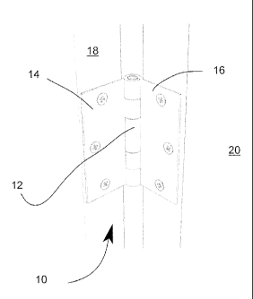
[0024] Fig. 1 Isometric view of the invention in context.
[0025] Figs. 2a-c Top, side, and front views, respectively, of the door flap.
CA 02752764 2016-01-15
7
[0026] Figs. 3a-c Top, side, and front views, respectively, of the jamb flap.
[0027] Figs. 4a-b Side and bottom views, respectively, of the pin.
[0028] Figs. 5a-b Side and bottom views, respectively, of the locking pin.
DETAILED DESCRIPTION
[0029] A quick release door hinge system (10) has a locking pin (12) and two
flaps (14, 16): A jamb flap (14) that is fixedly attached to a door jamb (18)
and a door flap (16) which is fixedly attached to a door (20). The door
flap (16) has built-in downwardly pointing pins (22) that are configured
and sized to fit into door flap channels (24) found on the jamb flap (14).
Once the two flaps (14, 16) are connected, the locking pin (12) is
configured and sized to be frictionally inserted between the pins (22) and
the channels (24) so as to block any upward motion of the door flap (16)
which could not only result in an inadvertent release of the door (20) from
its quick release door hinge system (10) but most importantly, prevents
potential removal of the door (20) by robbers or any such unwanted
removal from the quick release door hinge system (10). To further
improve the frictional insertion, the locking pin (12) can be magnetized to
better cling to the ferrous hinge system (10). Better yet, the pins (22), as
CA 02752764 2016-01-15
8
seen in figs. 4a-b, can have a magnetic core (23) presenting opposing
polarities so as to increase the strength of the connection between the
pins (22) and the locking pin (12).
[0030] It should be noted that the location of the flaps (14, 16) can be
reversed,
that is, the jamb flap (14) can be installed on the door (20) and vice
versa. This configuration can help in the lubrication of the hinge (10).
Also, the locking pin is preferably a magnet so that it can more easily
stay in place.
[0031] Moreover, because of symmetry in construction, more specifically the
way the barrels (27) are centrally located on the vertical axis, as seen in
fig. 3a, as opposed to affset as seen in fig. 2a, they can be placed on the
left or the right of a door. Also, screw holes (29) have a bevel (25) located
on both sides so that both faces of the jamb flap (14), as seen in fig. 3a,
as opposed to a one side bevel as seen in fig. 2a, can be used equally
well on the left or on the right side of a door. The door flap (16) also has
the same barrel (27) and bevel (25) configuration for use on the left hand
side as well as the right hand side.
[0032] In order to release the door (20), a user simply removes the locking
pin
(12) by pushing it with a finger; opens the door (20) and; lifts the door
CA 02752764 2016-01-15
9
(20) so that the downwardly pointing pins (22) are released from the
jamb flap channels (24'). Reversing the steps allows for quick re-
installation of the door (20).
[0033] With respect to the above description then, it is to be realized that
the
optimum dimensional relationships for the parts of the invention, to
include variations in size, materials, shape, form, function and manner
of operation, assembly and use, are deemed readily apparent and
obvious to one skilled in the art, and all equivalent relationships to those
illustrated in the drawings and described in the specification are
intended to be encompassed by the present invention.
[0034] Therefore, the foregoing is considered as illustrative only of the
principles of the invention. Further, since numerous modifications and
changes will readily occur to those skilled in the art, it is not desired to
limit the invention to the exact construction and operation shown and
described, and accordingly, all suitable modifications and equivalents
may be resorted to, falling within the scope of the invention.