Note : Les descriptions sont présentées dans la langue officielle dans laquelle elles ont été soumises.
CA 02758871 2015-02-13
REMOVAL OF METALS FROM WATER
FIELD OF THE INVENTION
[0002] The invention relates to purifying water. In particular, the
invention relates to an efficient electrolytic method for removing metal ions
from
water in the presence of sacrificial reductants, such as urea, ammonia or a
combination thereof.
BACKGROUND
[0003] Ammonia, urea, and metals are species that are commonly
presented in wastewater that is derived from different sources, e.g.,
industrial,
livestock, ships, hydrometallurgy, electronics, and the like.
[0004] There are different processes that allow the removal of these
species individually, including for example, chemical precipitation, ion
exchange, reverse osmosis, surface clay filtration, electrowinning,
electrodialysis, air/steam stripping, anaerobic biological
oxidation/nitrification,
and breakpoint chlorination. However, none of these processes provide the
capability of performing the removal of the aforementioned species
simultaneously. Moreover, the required regulatory limits or the desired low
levels cannot be achieved efficiently.
[0005] For example, electrowinning may be used for the removal of metal
ions in aqueous solutions. And while electrowinning can recover 90 to 95% of
the available metal ions, it is known to operate efficiently only at high
metal ion
concentrations. For example, as the concentration of the metal ions decrease
to lower concentrations, such as about 500 mg/L (parts per million or ppm) or
less, higher voltages and/or current densities must be used. At these low
concentration conditions, the excess electrical energy is diverted into
producing
-1-
CA 02758871 2011-10-13
WO 2010/120882
PCT/US2010/031033
hydrogen at the cathode, which thereby competes with the reduction of the
metal. Moreover, a substantial amount of energy is consumed by the hydrogen
generation. As such, as the low levels required by regulatory agencies, such
as
the Environmental Protection Agency, are approached, the process becomes
increasingly less efficient.
[0006] Further, anaerobic biological oxidations may be used for the
removal of ammonia. However, these methods require a strict control of the pH
to keep the bacteria alive, and require long retention times. Moreover, these
processes have not been shown to be applicable for the removal of metals from
waste water.
[0007] Osmosis can be used to filter water from impurities, but it
does not
ultimately remove the impurities and instead merely concentrates them. In
addition, removal of ammonia by this process requires expensive membranes
and high pressure.
[0008] Therefore, a need still exists for an efficient and
simultaneous
method for removing metals, and urea and/or ammonia from waste water.
SUMMARY OF THE INVENTION
[0009] The present invention is premised on the realization that the
simultaneous removal of multiple impurities from waste water can be
efficiently
achieved to provide clean water. More particularly, the present invention is
premised on the realization that metal ions and a sacrificial reductant, such
as
urea and/or ammonia, can be efficiently removed from waste water via
electrolysis using an electrolytic cell.
[0010] In accordance with the present invention, a method of
purifying
water is provided. The method includes applying a voltage to an electrolytic
cell
that comprises an anode, a cathode and an alkaline electrolyte composition
having a pH value of about 11 or less. The alkaline electrolyte composition
comprises at least one metal ion to be reduced, and a sacrificial reductant.
Moreover, the voltage is applied across the cathode and the anode that is
sufficient to reduce the at least one metal ion to form at least one elemental
metal species at the cathode, and to oxidize the sacrificial reductant at the
anode, and wherein the voltage is less than a value necessary to affect a
-2-
CA 02758871 2015-02-13
substantial generation of hydrogen at the cathode and/or a substantial
generation of oxygen at the anode.
[0010.1] In accordance with one aspect of the present invention, there is
provided a method of purifying water comprising applying a voltage to an
electrolytic cell comprising a cathode with a first conducting component, an
anode with a second conducting component selected from the group consisting
of cobalt, copper, iron, nickel, platinum, iridium, ruthenium, rhodium, and
mixtures thereof and alloys thereof, and an alkaline electrolyte composition
in
electrical communication with the anode and the cathode, wherein the alkaline
electrolyte composition has a pH value of 11 or less and wherein the alkaline
electrolyte composition comprises at least one waste metal ion to be reduced,
and a sacrificial reductant selected from the group consisting of urea,
ammonia,
ethanol, methanol and a combination thereof, wherein the voltage is applied
across the cathode and the anode and is sufficient to reduce the at least one
waste metal ion to form at least one elemental metal species at the cathode,
and
to oxidize the sacrificial reductant at the anode, and wherein the voltage is
less
than a value necessary to affect a substantial generation of hydrogen at the
cathode and/or a substantial generation of oxygen at the anode.
[0010.2] In accordance with another aspect of the present invention, there
is
provided a method of removing metal ions from water comprising, the method
comprising applying a voltage to an electrolytic cell comprising a cathode
with a
first conducting component, an anode with a second conducting component
selected from the group consisting of cobalt, copper, iron, nickel, platinum,
iridium, ruthenium, rhodium, and mixtures thereof and alloys thereof, and an
alkaline electrolyte composition in electrical communication with the anode
and
the cathode, wherein the alkaline electrolyte composition has a pH value of 11
or
less and wherein the alkaline electrolyte composition comprises at least one
waste metal ion to be reduced, and a sacrificial reductant selected from the
group consisting of urea, ammonia, ethanol, methanol, and a combination
thereof, wherein the voltage is applied across the cathode and the anode and
is
sufficient to reduce the at least one waste metal ion to form at least one
elemental metal species at the cathode, and to oxidize the sacrificial
reductant at
the anode, and wherein the voltage is less than a value necessary to affect a
-3-
CA 02758871 2015-02-13
substantial generation of hydrogen at the cathode and/or a substantial
generation of oxygen at the anode.
[0011] The objects and advantages of the present invention will be
further appreciated in light of the following detailed description and example
in
which:
BRIEF DESCRIPTION OF THE DRAWINGS
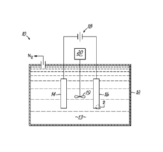
[0012] FIG. 1 is a diagrammatical view of a simplified electrolytic cell
configured for batch processing;
[0013] FIG. 2 is a cross-sectional view of a cathode in the electrolytic
cell shown in FIG. 1; and
[0014] FIG. 3 is a diagrammatical view of a simplified electrolytic cell
configured for flow cell processing.
DETAILED DESCRIPTION OF THE INVENTION
FIG. 1 is a diagrammatic depiction of a simplified electrolytic cell 10
configured for batch processing to achieve the simultaneous removal of metal
ions and a sacrificial reductant, such as urea and/or ammonia. A simplified
electrolytic cell 10 representing a single batch-type arrangement comprises a
tank 12, which may be made of light gauge iron, steel or other material not
attacked by an alkaline electrolyte composition 13. An electrode assembly
comprising an anode 14 and a cathode 16 is suspended within an alkaline
electrolyte composition 13 contained in tank 2 that may be agitated or stirred
by agitator 19 rotated by motor 20. In this single batch-type arrangement, the
alkaline electrolyte composition 13 includes at least one metal ion species,
as
well as an effective amount of a sacrificial reductant, such as urea and/or
ammonia, as described below. The anode 14 and cathode 16 are electrically
connected to a voltage source 18, which provides the electrical energy for the
simultaneous reduction of the at least one metal ion species and the oxidation
of the sacrificial reductant, such as urea and/or ammonia present in the
alkaline electrolyte composition 13. It will be readily apparent to one of
ordinary skill in the art that the above cell is readily adaptable to a
continuous
flow cell configuration, which is schematically shown in FIG. 3 and discussed
-3a-
CA 02758871 2011-10-13
WO 2010/120882
PCT/US2010/031033
further below. Further it may be appreciated that multiple electrolytic cells
may
be used in combination, either in series configuration, parallel
configuration, or
a combination thereof.
[0016] Embodiments of the present invention find their application on
the
removal of metals and a sacrificial reductant, such as ammonia and/or urea,
from water. Waste water may be purified with high efficiency, as well as, to
levels that satisfy regulatory limits for discharge of the purified water to
the
environment. Further, it should be appreciated that the present method may be
used for the recovery of metals in different industrial processes.
[0017] In the present invention, the metal ions are removed from the
waste water by the reduction of a cationic metal species (i.e., oxidized
metal) to
the elemental form of the metal, which occurs at the cathode 16, according to
the following general equation:
Equation 1: M+x + x e- ¨> M
wherein x is an integer representing the oxidation state of the metal (M). As
the
metal ions convert to the elemental form at the cathode 16, the elemental
metal
is deposited on the cathode 16.
[0018] According to the present invention, the waste water includes
metals in the form of cations, (i.e., oxidized forms of a metal). By way of
example, but without limitation, metals amenable to the present method of
electrochemical purification of waste water include zinc, chromium, tantalum,
gallium, iron, cadmium, indium, thallium, cobalt, nickel, tin, lead, copper,
bismuth, silver, mercury, chromium, niobium, vanadium, manganese,
aluminum, and combinations thereof. Accordingly, one metal suitably removed
from an aqueous sample included nickel.
[0019] According to embodiments of the present invention, the waste
water may include metal concentrations from about 500 pm and lower. For
example, from about 250 ppm and lower, from about 100 ppm and lower, or
from about 50 ppm and lower. Moreover, the purified water obtained from the
above the above waste water samples may have metal concentrations
sufficiently low to permit direct discharge to the environment without further
processing.
-4-
CA 02758871 2011-10-13
WO 2010/120882
PCT/US2010/031033
[0020] According to embodiments of the present invention, the waste
water may include a sacrificial reductant, such as urea or ammonia, which
effectively lowers the electrochemical potential of the electrolytic cell.
Advantageously, waste water may contain a sufficient quantity of a sacrificial
reductant, such as urea or ammonia from urine, which would thereby permit the
removal of one or more waste metals, along with urea and/or ammonia,
simultaneously. It should be appreciated by skilled artisans that other
sacrificial
reductants, such as ethanol or methanol, may also be adaptable to
embodiments of the present invention.
[0021] The electrodes, (i.e., anode 14 and cathode 16) may each
comprise a conductor or a support that can be coated with a more active
conducting component. The conducting component of the cathode 16 is not
particularly limited to any species of conductor, but the conducting component
should be comprised of a substrate whereon the metal can deposit. For
example, the conducting component of the cathode 16 may comprise carbon,
such as carbon fibers, carbon paper, glassy carbon, carbon nanofibers, carbon
nanotubes, and the like; or conducting metals, such as cobalt, copper,
iridium,
iron, nickel, platinum, palladium, ruthenium, rhodium and mixtures and alloys
thereof.
[0022] Thus, as shown in FIG. 2, an exemplary cathode 16 shows an
underlying support material 26 that has been coated with a layer of an active
conducting component 22 that is compatible with electrodepositing the reduced
waste metal. A deposited waste metal layer 24 forms on the layer of the active
conducting component 22, to provide purified water.
[0023] Moreover, metal deposition rates are related to the available
surface area. As such, large surface area substrates are generally preferred.
The cathode substrate should be able to withstand alkaline conditions.
Examples of substrates include: conductive metals, carbon fibers, carbon
paper, glassy carbon, carbon nanofibers, carbon nanotubes, and the like. For
example, the conductive metal of the cathode substrate may be cobalt, copper,
iridium, iron, nickel, platinum, palladium, ruthenium, rhodium and mixtures
and
alloys thereof. In another example, the cathode 16 comprises platinum, such
as platinum deposited on carbon paper.
-5-
CA 02758871 2015-02-13
[0024] In the present invention, the oxidation of a sacrificial reductant
occurs at the conducting component of the anode 14 in an alkaline electrolyte
composition or medium. Exemplary sacrificial reductants urea and ammonia are
oxidized at the conducting component of the anode 14 in an alkaline
electrolyte
medium according to the following equations:
Equation 2: 2 NH3+ 6 01-1" ¨> N2 + 6 H20 + 6 e- (-0.77 V vs.
SHE)
Equation 3: CO(NH2)2 + 6 OH- ¨> N2 + 5 H20 + CO2 + 6 e- (-0.034 V vs. SHE)
Therefore, the conducting component of the anode 14 may be one or more
metals active toward adsorbing and oxidizing the sacrificial reductants urea
and/or ammonia.
[0025] For example, one or more metals active toward the oxidation of
ammonia include metals disclosed in commonly-assigned U.S. Patent No.
7,485,211. By way of further example, the removal of ammonia may be
performed with a conducting component comprising platinum, iridium, ruthenium,
rhodium and their combinations. The conducting component may be co-
deposited as alloys and/or by layers.
[0026] Additionally, metals active toward the oxidation of urea include
metals disclosed in commonly-assigned U.S. Patent Application Publication No.
2009/0095636. For example, the removal of urea may be performed with a
conducting component comprising transition metals, such as nickel; or precious
metals such as platinum, iridium, ruthenium, rhodium; and their combinations.
Especially effective metals for the oxidation of urea include nickel and other
transition metals. The metals may be co-deposited as alloys and/or by layers.
Moreover, the active metals may be in an oxidized form, such as nickel
oxyhydroxide.
[0027] Further, metals active toward the oxidation of ethanol and
methanol include metal disclosed in commonly-assigned U.S. Patent Application
Publication No. 2008/0318097.
-6-
CA 02758871 2011-10-13
WO 2010/120882
PCT/US2010/031033
[0028] By way of example and without limitation, the anode 14 may
comprise nickel electrodeposited on a carbon support, such as carbon fibers,
carbon paper, glassy carbon, carbon nanofibers, or carbon nanotubes, or nickel
formed into beads and suspended in a nickel gauze.
[0029] One electrode found to be favorable to the oxidation of urea
is an
activated nickel oxyhydroxide modified nickel electrode (NOMN). For example,
the NOMN electrode may be comprised of metallic substrates (Ni foil, Ni gauze,
Ti foil and Ti gauze) that have been electroplated with Ni using a Watts bath.
Specifically, the plated nickel electrode may be activated by being immersed
in
a solution containing nickel sulfate, sodium acetate, and sodium hydroxide at
33 C. Stainless steel may be used as a counter electrode. The plated nickel
electrode may be used as the anode and cathode by manual polarity switching
at 6.25 A/m2 for four 1 minute cycles and 2 two minute cycles. Finally, the
electrode may be kept as the anode at the same current and maintained thereat
for two hours. The activated electrodes yield higher current densities than
those of M/Ni, where M represents a metallic substrate.
[0030] While anodes having large surface areas are favorable, the
structure of the anode 14 is not limited to any specific shape or form. For
example, the conducting component may be formed as foil, wire, gauze, bead
or coated onto a support. Suitable anode 14 support materials may be chosen
from many known supports, such as foils, meshes and sponges, for example.
The support material may include, but is not limited to, Ni foils, Ti foils,
carbon
fibers, carbon paper, glassy carbon, carbon nanofibers, and carbon nanotubes.
Aside from these specific support materials listed, other suitable supports
will
be recognized by those of ordinary skill in the art.
[0031] According to embodiments of the present invention, an alkaline
electrolyte composition 13 is used in the process. The alkaline electrolyte
composition 13 may include any suitable hydroxide salt. An alkali metal
hydroxide or alkali earth metal hydroxide salt, such as lithium hydroxide,
rubidium hydroxide, cesium hydroxide, barium hydroxide, strontium hydroxide,
potassium hydroxide, sodium hydroxide, magnesium hydroxide, calcium
hydroxide, and mixtures thereof may be used. In particular, the alkaline
electrolyte composition 13 includes potassium hydroxide.
-7-
CA 02758871 2011-10-13
WO 2010/120882
PCT/US2010/031033
[0032] Moreover, the alkaline electrolyte composition 13 may be a
solution, as shown in FIG. 1. Accordingly, the concentration of hydroxide
should be sufficiently low to avoid precipitation of a metal hydroxide form of
the
metal targeted for removal. Accordingly, the concentration of hydroxide used
for a particular system may be estimated from the solubility product of the
metal
hydroxide under consideration. Generally, a concentration of hydroxide higher
than 0.2 M is not recommended during the electrolytic removal of metals
according to the present invention. For example, to avoid precipitating the
metal hydroxide form of many of the metals ions listed above, the pH value is
advantageously about 11 or less. As yet another example, the pH may have a
value within a range from about 8 to about 11, or within a range from about 9
to
about 10.
[0033] In an alternative embodiment, the alkaline electrolyte
composition
may comprise a gel, such as a solid polymer electrolyte. Suitable alkaline
electrolytic gels include, for example, those gels containing polyacrylic
acid,
polyacrylates, polymethacrylates, polyacrylamides, sulfonated-polymers and
similar polymers and copolymers.
[0034] The alkaline electrolytic gel may be prepared using any
suitable
method. One method includes forming a polymer and then injecting the
hydroxide salt electrolyte into the polymer to form an alkaline electrolyte
gel or
polymeric mixture. In another method, the monomer may be polymerized in the
presence of a hydroxide salt electrolyte.
[0035] Although not shown in FIG. 1, a separator may be used to
compartmentalize the anode 14 and cathode 16. Separators should be
constructed from materials chemically resistant to the alkaline electrolyte
composition 13. Accordingly, many polymers are suitable for constructing
separators, such as Teflon and polypropylene. Further, separators may
comprise an alkaline electrolytic gel. While separators are not required for
simple batch-type arrangements, they may prove advantageous for continuous
flow electrochemical cells, as discussed next.
[0036] According to another embodiment of the present invention, a
flow
cell configuration is shown in FIG. 3, which provides a diagrammatic depiction
of a simplified electrolytic cell 30 for the simultaneous removal of metal
ions and
urea and/or ammonia from waste water. A simplified electrolytic cell 30
-8-
CA 02758871 2011-10-13
WO 2010/120882
PCT/US2010/031033
representing a flow cell arrangement comprises a housing 32, which may be
made of light gauge iron, steel or other material that is stabile in an
alkaline
medium. An electrode assembly comprising an anode 34 and a cathode 36 is
within the housing 32. In this flow cell arrangement, the anode 34 and the
cathode 36 are separated by a separator 39. The inlet port 31 permits the
introduction of the waste water that includes at least one metal ion species,
as
well as an effective amount of a sacrificial reductant, such as urea and/or
ammonia. Conversely, should the waste water be free of, or contain an
insufficient quantity of the sacrificial reductant, a second solution
containing the
desired concentration of a sacrificial reductant, such as ethanol, methanol,
urea, ammonia and combinations thereof, may be added separately through the
inlet port 33 to permit mixing with the waste water at the inlet junction 41.
The
anode 34 and the cathode 36 are electrically connected to a voltage source 38,
which provides the electrical energy for the reduction of the at least one
metal
ion species at the cathode 36 and for the oxidation of the sacrificial
reductant at
the anode 34 contained in the solution 35. The purified water exits the flow
cell
arrangement of electrolytic cell 30 through outlet 37.
[0037] According to one configuration, the pH value of the waste
water
may be adjusted to the desired range prior to introduction to the electrolytic
cell
30. According to another configuration, the pH of the waste water may be
adjusted while being introduced to the electrolytic cell 30, for example, by a
separate solution of hydroxide salt. Accordingly, in one embodiment the
separate solution of hydroxide salt may also include a sacrificial reductant,
such
as urea and/or an ammonia solution. According to another embodiment, the
anode 34 may be coated with an alkaline electrolytic gel.
[0038] Electrolytic cells, such as 10 and 30 may operate over varying
ranges of temperature and pressure. The operating pressure may be about
atmospheric pressure or ambient pressure with no upper pressure limit other
than the physical limits of the reaction vessel. The operating temperature
range
may be from about the freezing point of the waste water to about 100 C and
may be related to the operating pressure of the electrolytic cell. At one
atmosphere of pressure, it is practical to keep the operating temperature to
about 80 C or less, because at higher temperatures it is difficult to maintain
ammonia in solution. For example, an acceptable operating temperature may
-9-
CA 02758871 2011-10-13
WO 2010/120882
PCT/US2010/031033
be within a range from about 000 to about 80 C; or from about 20 C to about
65 C. More specifically, an operating temperature within a range from about
20 C to about 30 C is particularly useful.
[0039] The present invention is not limited to any particular source
of
electricity. That is, electricity can be provided from renewable energy
sources:
wind, solar, etc., storage sources (batteries), and conventional grid power
generation.
[0040] But according to embodiments of the present invention, the
voltage difference applied across the anode 14 and the cathode 16 of the
electrochemical cell 10 is maintained at a value that provides for the
reduction
of the waste metal ions while avoiding substantial hydrogen generation at the
cathode or substantial oxygen generation at the anode. As used herein,
"substantial" hydrogen evolution and "substantial" oxygen evolution means that
less than about 20% of the electrical energy is spent generating hydrogen
and/or oxygen. In other words, about 80% or more of the applied voltage is
spent removing the waste metal ions. For example, in one embodiment, less
than about 10% of the electrical energy is spent generating hydrogen and/or
oxygen. In yet another embodiment, less than about 5% of the electrical energy
is spent generating hydrogen and/or oxygen. In yet another embodiment, less
than about 3% of the electrical energy is spent generating hydrogen and/or
oxygen. In one exemplary embodiment, the voltage applied across the anode
14 and the cathode 16 does not generate any hydrogen at the cathode.
[0041] According to embodiments of the present invention, the voltage
difference applied across the anode 14 and the cathode 16 of a single
electrolytic cell may be maintained at a voltage of about 1.1 volts or lower.
In
another exemplary embodiment, the single cell voltage difference may be at a
value between about 0.01 volts to about 1.1 volts. In yet another embodiment,
the single cell voltage may be at a value of about 0.2 volts to about 0.9
volts.
[0042] Thus, in accordance with embodiments of the invention, the
removal of ammonia and waste metals from waste water may be achieved by
simultaneously contacting the waste water with the anode 14 and the cathode
16 of the electrochemical cell 10, as shown in Figure 1, or the anode 34 and
the
cathode 36 of the electrochemical cell 30. At the anode (14 or 34) of the
electrochemical cell (10 or 30) the electro-oxidation of ammonia in alkaline
-10-
CA 02758871 2011-10-13
WO 2010/120882
PCT/US2010/031033
media takes place according to Equation 2 as discussed above, while at the
cathode (16 or 36) of the electrochemical cell (10 or 30) the reduction of the
waste metal species takes place according to Equation 1 to thereby deposit the
reduced waste metal on the cathode (16 or 36), as shown in cut-away view in
FIG. 2.
[0043] It will be readily appreciated by those skilled in the art of
electrochemistry that the reactions at the cathode (16 or 36) as well as the
applied voltage depend on the metal and/or metals present in solution.
Simultaneous removal of several waste metals can be achieved by operating
the cell at the voltage necessary for reducing the metal with the highest
reduction potential.
[0044] Moreover, it should be appreciated that the presence of a
sacrificial reductant, such as ammonia, which is oxidized at the anode,
permits
the voltage applied to the electrochemical cell (10 or 30) to be sustained at
a
value wherein a substantial production of hydrogen does not take place at the
cathode (16 or 36), nor is a substantial production of oxygen occur at the
anode
(14 or 34). For example, waste metals such as zinc, chromium, tantalum,
gallium, iron, cadmium, indium, thallium, cobalt, nickel, tin, lead, chromium,
niobium, vanadium, manganese, aluminum, and combinations thereof can be
removed using a cell voltage that is sustained no higher than about 1.1 V.
[0045] Similar to that described above for ammonia, the removal of
urea
and waste metals from waste water may be achieved by simultaneously
contacting the waste water with the anode 14 and the cathode 16 of the
electrochemical cell 10, as shown in Figure 1, or the anode 34 and the cathode
36 of the electrochemical cell 30. At the anode (14 or 34) of the
electrochemical cell (10 or 30) the electro-oxidation of urea in alkaline
media
takes place according to Equation 3 as discussed above, while at the cathode
(16 or 36) of the electrochemical cell (10 or 30) the reduction of the waste
metal
species takes place according to Equation 1 to thereby deposit the reduced
waste metal on the cathode (16 or 36).
[0046] Moreover, it should be appreciated that the presence of urea,
which is oxidized at the anode, permits the voltage applied to the
electrochemical cell (10 or 30) to be sustained at a value where the reduction
of
hydrogen does not take place at the cathode (16 or 36) and oxygen is not
-11-
CA 02758871 2015-08-14
generated at the anode (14 or 34). For example, waste metals such as zinc,
chromium, tantalum, gallium, iron, cadmium, indium, thallium, cobalt, nickel,
tin,
lead, copper, bismuth, silver, mercury, and combinations thereof can be
removed
using a cell voltage that is sustained no higher than about 1.1 V.
[0047] According to the foregoing, it should be readily apparent that the
electrolytic
method disclosed provides for the simultaneous removal of the waste metal,
ammonia and urea, by modifying the anode (14 or 34) of electrochemical cell
(10 or
30) to facilitate the oxidation of urea and ammonia.
[0048] The present invention will be further appreciated in view of the
following example.
EXAMPLE
[0049] An electrochemical cell was built for the removal of ammonia and
nickel from a synthetic waste solution. The synthetic waste solution was
prepared
by combining nickel (II) sulfate, ammonium sulfate and potassium hydroxide in
DI
water in appropriate amounts to prepare 250 milliliters of a solution having:
Ni(II) =
31.25 ppm (mg/I), NH3 = 0.05 M, and KOH= 0.05 M. The synthetic waste solution
had a pH value of 10, as measured by a pH meter.
[0050] The anode of the cell was constructed of platinum deposited on
carbon paper (2 cm x 2 cm), while the cathode of the cell was a nickel foil (2
cm x 4
cm). The electrochemical cell was operated at 25 C while at atmospheric
pressure and a constant voltage of 0.9 V was applied. A constant current of 10
mA
was observed during the operation of the cell. After 1 hour, 1 mg of nickel
metal
was deposited at the cathode of the cell, which calculated to be an efficiency
of
about 100% for the deposition of nickel [Ni (II) + 2e- Ni (0)] according to
Faraday's Law. The cathode of the cell was analyzed by scanning electron
microscopy and X-ray diffraction to confirm the deposition of nickel.
[0051] While the present invention has been illustrated by the
description of
one or more embodiments thereof, and while the embodiments have been
described in considerable detail, additional advantages and modifications will
readily appear to those skilled in the art. Accordingly, departures may be
made
from such details. The scope of the claims should not be limited by the
preferred
embodiments set forth in the examples, but should be given the broadest
interpretation consistent with the description as a whole.
-12-