Sélection de la langue

Search

Sommaire du brevet 2386708 

Énoncé de désistement de responsabilité concernant l'information provenant de tiers

Une partie des informations de ce site Web a été fournie par des sources externes. Le gouvernement du Canada n'assume aucune responsabilité concernant la précision, l'actualité ou la fiabilité des informations fournies par les sources externes. Les utilisateurs qui désirent employer cette information devraient consulter directement la source des informations. Le contenu fourni par les sources externes n'est pas assujetti aux exigences sur les langues officielles, la protection des renseignements personnels et l'accessibilité.

Disponibilité de l'Abrégé et des Revendications

L'apparition de différences dans le texte et l'image des Revendications et de l'Abrégé dépend du moment auquel le document est publié. Les textes des Revendications et de l'Abrégé sont affichés :

  • lorsque la demande peut être examinée par le public;
  • lorsque le brevet est émis (délivrance).
(12) Brevet: (11) CA 2386708
(54) Titre français: SOUPAPE DE POMPE
(54) Titre anglais: A PUMP VALVE
Statut: Périmé
Données bibliographiques
(51) Classification internationale des brevets (CIB):
  • F16K 15/03 (2006.01)
  • F16K 1/18 (2006.01)
  • F16K 15/02 (2006.01)
(72) Inventeurs :
  • SANTA, JOSEPH LUIZ (Australie)
(73) Titulaires :
  • JOE SANTA & ASSOCIATES PTY. LIMITED (Australie)
(71) Demandeurs :
  • JOE SANTA & ASSOCIATES PTY. LIMITED (Australie)
(74) Agent: ROBIC
(74) Co-agent:
(45) Délivré: 2009-07-14
(22) Date de dépôt: 2002-05-17
(41) Mise à la disponibilité du public: 2002-11-30
Requête d'examen: 2006-12-14
Licence disponible: S.O.
(25) Langue des documents déposés: Anglais

Traité de coopération en matière de brevets (PCT): Non

(30) Données de priorité de la demande:
Numéro de la demande Pays / territoire Date
PR5343 Australie 2001-05-30

Abrégés

Abrégé français

Élément de soupape de fluide unidirectionnelle (10) destiné à être monté sur un corps de soupape (12) ayant une ouverture (18) entourée d'un siège de soupape (16). L'élément de soupape (10) comprend un élément de fermeture de soupape (14) destiné à être fixé de manière détachable sur le corps (12) afin de lui permettre de bouger par rapport à celui-ci entre une première position de prise avec le siège (16), qui empêche le fluide de passer à travers l'ouverture (18) dans une direction, et une deuxième position à distance du siège (16), qui permet au fluide de passer à travers l'ouverture (18) dans une direction opposée à la direction prédéterminée. La partie de fermeture de la soupape (14) comporte une surface convexe servant à entrer dans le siège (16) de manière à s'avancer en saillie dans l'ouverture (18).


Abrégé anglais

A one-way fluid valve member (10) to be mounted on a valve (12) body having a valve opening (18) surrounded by a valve seat (16). The valve member (10) includes,: a valve closure part (14) to be movably mounted on the body (12) for movement relative thereto between a first position engaging the seat (16) to prevent movement of fluid through the opening (18) in a predetermined direction, and a second position spaced from the seat (16) to allow fluid to pass through the opening (18) in a direction opposite the predetermined direction; and wherein the valve closure part (14) has a convex surface to engage the seat (16) so as to project into the opening (18).

Revendications

Note : Les revendications sont présentées dans la langue officielle dans laquelle elles ont été soumises.


4
WHAT IS CLAIMED IS:

1. A one-way fluid valve member to be mounted on a valve body
having a valve opening surrounded by a valve seat located in a plane, said
valve
member including:
a valve closure part to be movably mounted on said valve body for
movement relative to said valve body by flow of said fluid in predetermined
and
opposite directions between a first position engaging said valve seat to
prevent
said flow of said fluid through said opening in said predetermined direction,
and
a second position spaced from said valve seat to allow fluid to pass through
said
opening in said opposite direction; and
a hinge member to mount said valve closure part on said body and
including a pivot portion, the pivot portion being spaced from said valve
closure
part in said opposite direction, and at least one arm attaching said valve
closure
part to said pivot portion, said hinge member and valve closure part defining
a
channel for flow of said fluid,
wherein said valve closure part maintains its configuration during said
movement, said movement being at least partly provided by resilient
deformation of said pivot portion, and
a portion of said pivot portion is spaced in said opposite direction over
said arm for preventing said second position of said valve closure part from
projecting in said opposite direction sufficiently that flow of said fluid in
said
predetermined direction will not move said valve closure part to said first
position.

2. A one-way fluid valve member according to claim 1, wherein said
valve closure part includes a pair of longitudinally extending arms attaching
said
valve closure part to said pivot.

3. A one-way fluid valve member according to claim 2, wherein said
arms are flexible.


5
4. A one-way fluid valve member according to claim 1, wherein said
valve member is of a unitary construction.

5. A one-way fluid valve member according to claim 2, wherein said
valve member is of a unitary construction.

6. A one-way fluid valve member according to claim 3, wherein said
valve member is of a unitary construction.

7. A one-way fluid valve member according to claim 1, wherein said
valve closure part has a convex top and bottom surface, said bottom surface to
engage said seat so as to project into said opening.

Description

Note : Les descriptions sont présentées dans la langue officielle dans laquelle elles ont été soumises.


CA 02386708 2008-07-31
1

A PUMP VALVE
Field of the Invention

The present invention relates to pumps and more par-ticularly but not
exclusively
to a flap valve for a pump.

Background of the Invention

Common valve assemblies (such as that disclosed in the Applicant's
Intemational Application PCT/AU93/00686 (W093118305)) are generally made in
three
pieces and include a first hinge.d plate, a valve, a further hinged plate and
nuts cooperating
with screw inserts to form a valve assembly. Under the influence of pressure,
th.e hinge
valve (or flap) pivots to open or close the valve opening. In this type of
"three-piece"
arrangement it has been found that problems arise when solids are caught under
the hinge
plate (flap). The obstructions have been found to prevent complete closure,
resulting in a
loss of vacuum causing the pump to stop.
It is therefore desirable to provide a one-piece valve assembly which
overcomes
these problems by having a lugher hinge point and a more penetrating closure
mechanism. This type of arrangement would also be effected less by the build
up of
solids due to its better clearance.

Object of the Invention

It is the object of the present invention to overcome or substantially
ameliorate at
least one of the above disadvantages or to provide a useful alternative.

Summary of the Inventiori

There is firstly disclosed herein a one-way fluid valve member to be
mounted on a valve body having a valve opening surrounded by a valve seat
located in a plane, said valve member including:
a valve closure part to be movably mounted on said valve body for
movement, relative to said valve body by flow of said fluid in predetermined
and
opposite directions between a first position engaging said valve seat to
prevent
said flow of said fluid through said opening in said predetermined direction,
and


CA 02386708 2008-07-31

2
a second position spaced from said valve seat to allow fluid to pass through
said
opening in said opposite direction; and
a hinge member to mount said valve closure part on said body and
including a pivot portion, the pivot portion being spaced from said valve
closure
part in said opposite direction, and at least one arm attaching said valve
closure
part to said pivot portion, said hinge member and valveclosure part defining a
channel for flow of said fluid,
wherein said valve closure part maintains its configuration during said
movement, said. movement being at least partly provided by resilient
deformation of said pivot portion, and
a portion of said pivot portion is spaced in said opposite direction over
said arm for preventing said second position of said valve closure part from
projecting in said opposite direction sufficiently that flow of said fluid in
said
predetermined direction will not move said valve closure part to said first
position.

There is further disclosed herein a one-way fluid valve member to be moi.inted
on a valve body having a valve opening surrounded by a valve seat, said valve
meinber
including:
a valve closure part to be movably mounted on said body for movement relative
thereto between a flrst position engaging said seat to prevent movement of
fluid through
said opening in a predetermined direction, and a second position spaced from
the seat to
allow fluid to pass tluougli said opening in a direction opposite said
predetermined
direction; .
a hinge member to mount said valve part on said body, said hinge member being
resiliently deformed to provide for said movement; and wherein
said valve closure part maintains its configuration during movenient as said
hinge resiliently deforms.
Preferably, saici valve seat is located in a plane, and said valve member is
coimected to said body by a pivot spaced from said plane opposite said
predetermined
direction.
Preferably, said valve member is of a unitary constniction.


CA 02386708 2008-07-31

2a
Preferably, said valve part includes a pair of longitudinally extending arms
coiuiected to said pivot.
Preferably, said arms are flexible.
Preferably, said space defines a channel for fluid flow.

Preferably, said valve closure part has a convex top and bottom surface,
said bottom surface to engage said seat so as to project into said opening.

Brief Description of the Drawings

A preferred form of the present invention will now be described by way of
example only with reference to the accompanying drawings wherein:
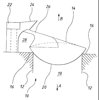
Figure I is schematic side view of a valve member in accordance with an
embodiment of the invention;
Figure 2 is a bottom view of the valve of Figure 1;
Figure 3 is a top view of the valve of Figure 1;
Figure 4 is a front view of the valve of Figure 1; and;
Figure 5 is a rear view of the valve of Figure 1.

Detailed Description of the Preferred Embodiments

In Figures I to 5 of the accompanying drawulgs, there is schematically
depicted
a one-,vay fluid valve member 10 to be mounted on a valve body 12. Valve body
12 is
- ------ ------ /.


CA 02386708 2002-08-28
-3-
part of a pump system which would normally include such features as a number
of punip
cliambers being interconnected to allo-,v fluid flow between a number of
inlets and outlets.
The valve member 10 is made of a unitar), construction and preferably out of
rubber or
similar type products. Valve mernber 10 includes a valve closure part 14
movably
s mounted on the body 12 for movement relative thereto between a-first
position engaging a
valve seat 16 to prevent niovement of fluid through a valve opening 18 in a
predetermined
direction (Arrow A) and a second position spaced from the seat 16 to allow
fluid to pass
through the opening in a direction opposite the predetermined direction (Arrow
B). The
valve closure part 14 has a convex surface 20 which is adapted to engage the
seat 16 and
project into the opening 18 as best shown in Figure 1.
The valve member 10 can further include a hinge member 22 mounted on the
body 12. 'T1ie hinge member projects away from the plane of the valve seat 16
opposite
the predetermined direction (Arrow B). The hinge member 22 includes a
resiliently
deformable hinge pivot portion 24 which is connected to the valve closure part
14 by a
is pair of longitudinal extending arms 26. In use, the valve part 14 maintains
its
configuration during movement whilst the hinge portion 24 resiliently deforms.
In one
preferred einbodiment, the arms 26 could also be deforrnable.
As best seen in Figure 1, when the hinge meinber 22 is displaced away from the
plane of tlie seat 16 (that is, in the direction of Arrow B) and the valve
closure part 14
(being coruiected to the hinge pivot portion 24) is in contact with the seat
16, a channe128
is formed which provides an avenue for fluid to flow without interfering or
preventing the
closure of valve closure part 14 with. the seat 16. 'I'his results in the
vacuum created
within the purnp system being maintained and stops any interruption to
pumping.
Further, due to the convex surface 20 of the valve part 14, better vacuum
closure can be
obtained further increasing the efficiency of the pump.
Although the invention has been described witlt reference to specific
examples, it
will be appreciated by those skilled in the art that the invention may be
embodied in many
other forms.

Dessin représentatif
Une figure unique qui représente un dessin illustrant l'invention.
États administratifs

Pour une meilleure compréhension de l'état de la demande ou brevet qui figure sur cette page, la rubrique Mise en garde , et les descriptions de Brevet , États administratifs , Taxes périodiques et Historique des paiements devraient être consultées.

États administratifs

Titre Date
Date de délivrance prévu 2009-07-14
(22) Dépôt 2002-05-17
(41) Mise à la disponibilité du public 2002-11-30
Requête d'examen 2006-12-14
(45) Délivré 2009-07-14
Expiré 2022-05-17

Historique d'abandonnement

Il n'y a pas d'historique d'abandonnement

Historique des paiements

Type de taxes Anniversaire Échéance Montant payé Date payée
Le dépôt d'une demande de brevet 300,00 $ 2002-05-17
Enregistrement de documents 100,00 $ 2002-07-29
Taxe de maintien en état - Demande - nouvelle loi 2 2004-05-17 100,00 $ 2004-04-22
Taxe de maintien en état - Demande - nouvelle loi 3 2005-05-17 100,00 $ 2005-04-22
Taxe de maintien en état - Demande - nouvelle loi 4 2006-05-17 100,00 $ 2006-04-20
Requête d'examen 800,00 $ 2006-12-14
Taxe de maintien en état - Demande - nouvelle loi 5 2007-05-17 200,00 $ 2007-04-18
Taxe de maintien en état - Demande - nouvelle loi 6 2008-05-19 200,00 $ 2008-04-16
Taxe de maintien en état - Demande - nouvelle loi 7 2009-05-18 200,00 $ 2009-04-20
Taxe finale 300,00 $ 2009-05-01
Taxe de maintien en état - brevet - nouvelle loi 8 2010-05-17 200,00 $ 2010-04-14
Taxe de maintien en état - brevet - nouvelle loi 9 2011-05-17 200,00 $ 2011-04-13
Taxe de maintien en état - brevet - nouvelle loi 10 2012-05-17 250,00 $ 2012-04-11
Taxe de maintien en état - brevet - nouvelle loi 11 2013-05-17 250,00 $ 2013-04-10
Taxe de maintien en état - brevet - nouvelle loi 12 2014-05-20 250,00 $ 2014-04-09
Taxe de maintien en état - brevet - nouvelle loi 13 2015-05-19 250,00 $ 2015-04-22
Taxe de maintien en état - brevet - nouvelle loi 14 2016-05-17 250,00 $ 2016-04-27
Taxe de maintien en état - brevet - nouvelle loi 15 2017-05-17 450,00 $ 2017-04-26
Taxe de maintien en état - brevet - nouvelle loi 16 2018-05-17 450,00 $ 2018-04-26
Taxe de maintien en état - brevet - nouvelle loi 17 2019-05-17 450,00 $ 2019-04-24
Taxe de maintien en état - brevet - nouvelle loi 18 2020-05-18 450,00 $ 2020-04-23
Taxe de maintien en état - brevet - nouvelle loi 19 2021-05-17 459,00 $ 2021-04-21
Titulaires au dossier

Les titulaires actuels et antérieures au dossier sont affichés en ordre alphabétique.

Titulaires actuels au dossier
JOE SANTA & ASSOCIATES PTY. LIMITED
Titulaires antérieures au dossier
SANTA, JOSEPH LUIZ
Les propriétaires antérieurs qui ne figurent pas dans la liste des « Propriétaires au dossier » apparaîtront dans d'autres documents au dossier.
Documents

Pour visionner les fichiers sélectionnés, entrer le code reCAPTCHA :


Pour visualiser une image, cliquer sur un lien dans la colonne description du document. Pour télécharger l'image (les images), cliquer l'une ou plusieurs cases à cocher dans la première colonne et ensuite cliquer sur le bouton "Télécharger sélection en format PDF (archive Zip)" ou le bouton "Télécharger sélection (en un fichier PDF fusionné)".

Liste des documents de brevet publiés et non publiés sur la BDBC .

Si vous avez des difficultés à accéder au contenu, veuillez communiquer avec le Centre de services à la clientèle au 1-866-997-1936, ou envoyer un courriel au Centre de service à la clientèle de l'OPIC.


Description du
Document 
Date
(yyyy-mm-dd) 
Nombre de pages   Taille de l'image (Ko) 
Page couverture 2002-11-15 1 33
Abrégé 2002-05-17 1 18
Dessins représentatifs 2002-10-01 1 6
Abrégé 2002-08-28 1 19
Description 2002-08-28 3 164
Revendications 2002-08-28 2 62
Dessins 2002-08-28 5 53
Description 2002-05-17 3 145
Revendications 2002-05-17 2 56
Dessins 2002-05-17 5 48
Revendications 2008-07-31 2 54
Description 2008-07-31 4 174
Dessins représentatifs 2009-06-16 1 8
Page couverture 2009-06-16 2 38
Correspondance 2002-06-27 1 28
Cession 2002-05-17 3 80
Cession 2002-07-29 2 66
Correspondance 2002-08-28 13 351
Poursuite-Amendment 2008-07-31 9 266
Poursuite-Amendment 2006-12-14 1 43
Poursuite-Amendment 2008-06-17 3 92
Correspondance 2009-05-01 2 54
Correspondance 2010-08-10 1 47